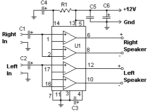
Here the circuit diagram of 22W stereo power amplifier. Powered with main power IC TDA1554Q, this circuit works up to 22W for each channel. For stereo channel, the power output? should be up to 2 x 22W . A few externel components required to support the main component. Heatsink on the power IC is a must to prevent the chip from over heat and maximize its performance.
Components List:
R1        : 39K 1/4 Watt Resistor
C1,C2     : 10uf 25V Electrolytic Capacitor
C3        : 100uf 25V Electrolytic Capacitor
C4        : 47uf 25V Electrolytic Capacitor
C5        : 0.1uf 25V Ceramic Capacitor
C6        : 2200uf 25V Electrolytic Capacitor
U1        : TDA1554Q Two Channel Audio Amp Chip
MISC      : Heatsink For U1, Binding Posts (For Output), RCA Jacks (For Input)
The? works best with 4 ohm speakers, but 8 ohm units will do. This circuit dissipates roughly 28 watts of heat, so a good heatsink is necessary. The chip should run cool enough to touch with the proper heatsink installed.
Operated at 12 Volts and at about 5 Amps at full volume. Lower volumes use less current, and therefore produce less heat. Printed circuit board is preferred, but universal solder or perf board will do. Keep lead length short.
The TDA1554Q is an integrated class-B output amplifier in a 17-lead single-in-line (SIL) plastic power package. The circuit contains 4 x 11 W single-ended or 2 x 22 W bridge amplifiers. The device is primarily developed for car radio applications.
Download TDA1554Q Datasheet Document:
[wpdm_file id=29]
Do you have a bicycle..? why don't try to build this circuit..?. Powered using battery…
This is the circuit diagram of 3A switching power supply regulator: Simple and cheap, the…
Here is the remote control tester circuit. This circuit is really a simple and easy…
This is the circuit diagram of current output multiplier designed for regulator IC LM78xx. By…
The following diagram is the FM tracking transmitter based on 4 transistors. No additional notes…
This is the circuit diagram of white line follower toy. The actuator of the toy…
View Comments
i need layout of tda1554q