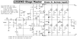
Here is the 250W RMS power amplifier circuit called Legend-Stage Master. This is the previous version of Legend-Stage Master MK2. The circuit is based on power MOSFET and give a great output performance for indoor audio sound system.
Over time there is a need for a stronger version of the legend and which serves to lower sound system for gigs and house parties. This gave improvement to this version called Stage Master which is basically not much different from the original. However, the yield and reliability of the power it was necessary to add a degree of excitation, because the output is assigned to two more pairs of MOSFETs, but the total need for excitation and the other parameters increased because of the parallel connection of so many of FET via abilities were VAS the degree of the basic versions.
Specifications:
> Output power : 250W RMS / 8 ohms
> Frequency range : 12Hz-230KHz (-1dB) at 10W RMS
> THD <0.12% (at 1 kHz and 250 W) > THD <0.01% (at 1 kHz and 200W and below this power) > BIAS around 50mA per output pair
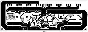
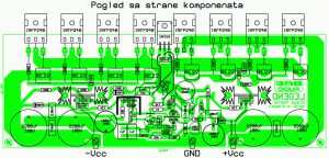
250W RMS Power Amplifier PCB Design and Layout
This is the PCB design and component placement for 250 RMS power amplifier, Legend-Stage Master version. In the design, the MOSFETs are both mounted on the PCB and heatsink. If you have difficulty making appropriate heatsink to be mounted on the PCB, you can separate the heatsink from the PCB, mount the MOSFET on the heatsink, then connect the pins of the MOSFET to a PCB using cable.
This circuit designed by Dr Borivoje Jagodic >> original page for the reference.

why did not you post a materials ,…. 🙁