Categories: AudioLinear Amplifier

50W Power Amplifier with STK-1050

This is the circuit diagram of??50W power amplifier based on audio power amplifier IC STK-1050. Symmetrical power supply used to operate this circuit with maximum voltage rated at 53V and recommended supply is 36V. This is a single channel (mono) amplifier circuit, for stereo audio system, you should build two similar circuit. Power supply with minimum 3A center tap transformer should be used for stereo amplifier.

Symmetrical power supply:

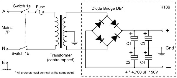
This is the sample of symmetrical / dual polarity power supply circuit diagram:

STK-1050 Features:

  1. Does not require externally connected emitter resistors.
  2. Values of emitter resistors have carefully been reviewed to provide superior characteristics.
  • Better supply voltage utilization permits designing power supply voltage that are about 0.7V (for RL=4ohms) lower than those required for previous DPP models.
  • Maximum allowable power consumption for each resistor is 5W or higher, permitting accomodation for all loads.
  • Peak allowable current is 18A or more, providing an ample margin even for peak currents under when short circuited or similar emergencies.
  • In particular, maximum output 4 ohms have been enormously improved.
  1. Use of emitter resistors facilitates meeting different safety standards and designing PCBs
  2. Mutual interferences in the high-frequency range caused by layout of externally connected emitter resistors no longer exist. This facilitates lower distortion factors.
  3. Pins are used for emitter resistor output terminals that were not conected in previous DPPs. All other terminals remain uncharged; there is no need for major circuit board changes.

Download STK-1050 datasheet for your project reference:
[wpdm_file id=63]

circuit schematic

View Comments

  • Hi! im interested 4 your stk power amp. can i have your board diagram and parts of your power amp plz.......?power amplifier IC STK-1050. ty.

Share
Published by
circuit schematic

Recent Posts

Switched ON Bike Lamp

Do you have a bicycle..? why don't try to build this circuit..?. Powered using battery…

54 years ago

3A Switching Power Supply Regulator

This is the circuit diagram of 3A switching power supply regulator: Simple and cheap, the…

54 years ago

Remote Control Tester

Here is the remote control tester circuit. This circuit is really a simple and easy…

54 years ago

Current Output Multiplier for 78xx Regulator

This is the circuit diagram of current output multiplier designed for regulator IC LM78xx. By…

54 years ago

4 Transistor FM Tracking Transmitter

The following diagram is the FM tracking transmitter based on 4 transistors. No additional notes…

54 years ago

White Line Follower

This is the circuit diagram of white line follower toy. The actuator of the toy…

54 years ago