Here the complete electrical circuit diagram of line follower robot which built based on ATmega16. There are three modules of line follower robot circuit that are sensor module, microcontroller module and DC motor module.
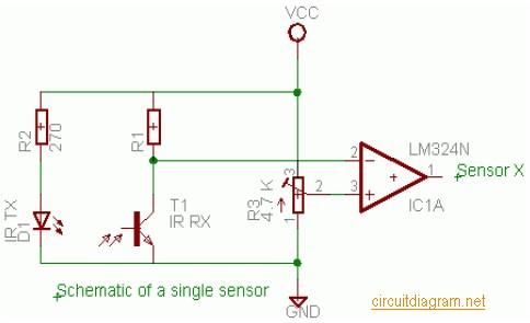
IR sensor schematic diagram:
The robot uses IR sensors to sense the line, an array of 8 IR LEDs (Tx) and sensors (Rx), facing the ground has been used in this setup. The output of the sensors is an analog signal which depends on the amount of light reflected back, this analog signal is given to the comparator to produce 0s and 1s which are then fed to the uC
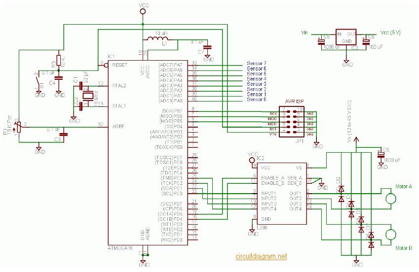
Mainboard (microcontroller + DC motor driver schematic diagram):
The L298 Motor Driver has 4 inputs to control the motion of the motors and two enable inputs which are used for switching the motors on and off. To control the speed of the motors a PWM waveform with variable duty cycle is applied to the enable pins. Rapidly switching the voltage between Vs and GND gives an effective voltage between Vs and GND whose value depends on the duty cycle of PWM. 100% duty cycle corresponds to voltage equal to Vs, 50 % corresponds to 0.5Vs and so on. The 1N4004 diodes are used to prevent back EMF of the motors from disturbing the remaining circuit. Many circuits use L293D for motor control, I chose L298 as it has current capacity of 2A per channel @ 45V compared to 0.6 A @ 36 V of a L293D. L293D’s package is not suitable for attaching a good heat sink, practically you can’t use it above 16V without frying it. L298 on the other hand works happily at 16V without a heat sink, though it is always better to use one.
Download the document of ATmega16 line follower robot tutorial for complete tutorial including the working explanation of circuit and program, source code and schematic diagram.
Do you have a bicycle..? why don't try to build this circuit..?. Powered using battery…
This is the circuit diagram of 3A switching power supply regulator: Simple and cheap, the…
Here is the remote control tester circuit. This circuit is really a simple and easy…
This is the circuit diagram of current output multiplier designed for regulator IC LM78xx. By…
The following diagram is the FM tracking transmitter based on 4 transistors. No additional notes…
This is the circuit diagram of white line follower toy. The actuator of the toy…
View Comments
Hi, and very thanks for great description but sadly the document link is broken so I couldn't get it. I'll be happy if you send it to my mail bcuz I need it very much
Nice discreption it helps the students.
Sir, please tell me the complete circuit diagram of line follower robot with microcontroller
Hi sir,I want to make a line follower robot without microcontroller, so please sir tell me the complete circuit diagram equipment required.
nyc discription it really hels me alot...........