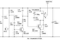
Here the simple and low cost FM transmitter circuit. The frequency range of this FM transmitter should be about 89MHz ? 109MHz. Output power is about 9mW at 9V. Components List: Resistors: R1, R6 : 12K […]
Author:
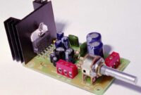
6-10W Stereo Audio Amplifier with IC TDA2005
Here the schematic diagram of 6-10W stereo power audio amplifier with IC TDA2005: Components List: R1, R9 ________ 1K ohm R2 ____________ 120K ohm R3, R4 ________ 1K2 ohm R5, R6 ________ 33 ohm R7, R8 […]
British Police Car Siren
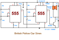
This is the sound generator which will simulate British police car siren. The circuit is built using 2 pieces of timer IC 555 to generate sound frequency. How the circuit work:
UHF TV Antenna Booster
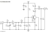
This is the circuit diagram of UHF band TV antenna booster with 15dB gain power. This low cost antenna booster is simple and easy to build.It use single transistor BF180 to boost te UHF signal. Since […]
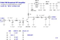
15W FM RF Amplifier with 2SC2539
This is a 15W FM RF amplifier circuit which build based on RF Power Transistor 2SC2539. 2SC2539 is a silicon NPN epitaxial planar type transistor designed for RF power amplifiers in VHF band mobile radio applications. […]
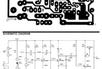
FM Wireless Microphone
Below is the circuit diagram and PCB layout of FM wireless microphone: The range of frequencies for the FM broadcast band is 90MHz (MHz = Megahertz or 90 million cycles per second). Because the FM microphone […]
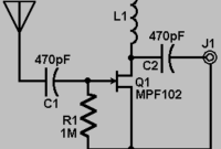
Active FM/AM/SW Radio Receiver Antenna
This is an active FM/AM/SW radio receiver antenna, can be used for FM radio receiver, AM radio receiver and SW (shortwave) radio receiver. This circuit use active component JFET VHF Amplifier MPF102 to boost the radio […]
Stereo Tone Control with LM1036
This is a stereo audio tone control circuit which build based on IC? LM1036. This circuit will controll bass/treble level tone, volume and balance between right channel and left channel (input 1 and 2 ). You […]
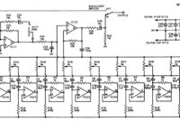
20 Band Graphic Equalizer
Here the 20 band graphic equalizer schematic diagram. This is stereo graphic equalizer, it should be 2×10 channel equalizer. Graphic equalizers device are popular with both domestic users and professional users. This equalizer is has simple […]
Running LEDs
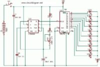
This is running LEDs circuit which use timer ID NE555N and logic IC 4017N. IC 555 act as a multivibrator and generate frequency to be used for 4017 clock input.

