
This is the circuit diagram of UHF band TV antenna booster with 15dB gain power. This low cost antenna booster is simple and easy to build.It use single transistor BF180 to boost te UHF signal.

Since this is an active circuit of UHF TV antenna booster, it will require a 12v power supply to operate. Regulated power supply is recommended for better circuit performance.
This circuit formed based on BF180 UHF Transistor. The first stage is an band pass filter constructed by the C1, CV1, L1, L4, C7 and C3, the second stage is a base-common voltage amplifier with low input impedance to match. After assembling, pack it into a proper metallic box and connect the ground of the circuit to the box to reduce noise effect.
The BF180 is equvilent NTE161 Transistor NPN Silicon VHF/UHF Amplifier Mixer/Oscillator. You mau try NTE161 transistor to replace the BF180.
Designing Air Core Inductor
An air core coil is an inductor formed by winding several turns of enameled wire on a none ferromagnetic cylinder that the cylinder can be removed after construction the coil.
The advantages of an air core coil are as follows:
- The inductance of coil is independent of the current, because there is no ferromagnetic core to saturate by the current increasing.
- There is no iron losses which affect ferromagnetic cores, then you can get better Q Factor and lower distortion as frequency is increased
- They can be used to operate truly at frequencies as high as 1 Ghz.
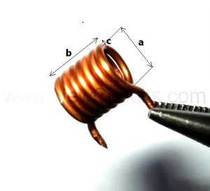
To calculate a single layer air core coil, see the above picture and use the following formula:
![]()
Where,
- L = Inductance in uH
- a = Average diameter of the coil in Inches
- b = Length of the coil in Inches
- c = Radial depth of the winding in Inches
- n = Total turns of wire
It is important to note that the formula will be true if value of b is greater than 0.4a .
A practical example:
Let’s calculate the inductance of coil in above picture. The mechanical specifications are as follows:
- a = 0.2480 Inches
- b = 0.3149 Inches
- c = 0.0866 Inches
- n = 7
Now we let them in the formula, then:


sir plese clear my confusion that
where is antena in put and tv in and out in this diagram
[COLOR=”Red”][SIZE=”6″]UHF TV Antenna Booster
[/SIZE][/COLOR]
I want to VHF and UHF tv high gain boster antena circuit diagram
hi, I looking for diagram to a tv DAYTEK model LCD32 year 2007, it is in Cuba a thunder burn a part
and the technician need a diagram to fix it, can you help?
thank