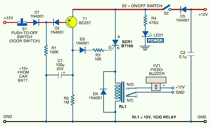
Image #1: Car Anti Theft Guard Circuit Design Diagram
This is the circuit diagram of car anti-theft to protect and increase the security of your car, prevent your from stealing. This circuit is very simple, low cost and easy to built. When key-operated switch S2 of the car is turned on, 12V DC supply from the car battery is extended to the entire circuit through polarity-guard diode D5. Blinking LED1 flashes to indicate that the car protection circuit is enabled. It works off 12V power supply along with current-limiting resistor R4 in series.
When the car door is closed, door switch S1 is in “on” condition and 12V power supply is available across resistor R1. This condition will? prevent transistor T1 from conducting. In this position, anti-theft protection circuit is in sleep mode.
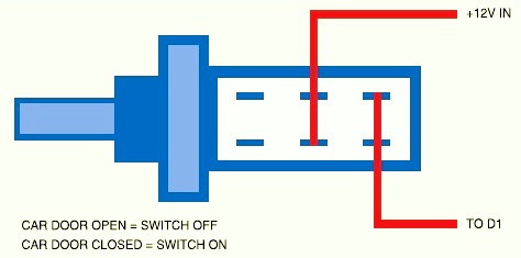
When someone opens the car door, switch S1 becomes “off” as shown in Image #2. As a result, transistor T1 conducts to fire relay-driver SCR1 (BT169) after a short delay introduced by capacitor C1. Electromagnetic relay RL1 energises and its N/O contact connects the power supply to piezobuzzer PZ1, which starts beeping to indicate that someone is make a try to steal your car. To reset the circuit, turn off switch S2 using car key. This will cutoff the power supply to the circuit, so the buzzer sound will be stopped.
Collect the circuit on an universal PCB and house in a little box suit to your car. Connect the switch S1 to th ecar door and keep piezobuzzer Pz1 at a suitable place in your car.
Do you have a bicycle..? why don't try to build this circuit..?. Powered using battery…
This is the circuit diagram of 3A switching power supply regulator: Simple and cheap, the…
Here is the remote control tester circuit. This circuit is really a simple and easy…
This is the circuit diagram of current output multiplier designed for regulator IC LM78xx. By…
The following diagram is the FM tracking transmitter based on 4 transistors. No additional notes…
This is the circuit diagram of white line follower toy. The actuator of the toy…
View Comments
What is the use of capacitor C2? please let me know