Here is the schematic design of car cigar lighter to USB power port. Nowadays, almost all computer systems have logic blocks for working with a USB port. In practice, a USB port is capable of supplying more than 100 mA of continuous electric current at 5V to the peripherals which are hooked up with the bus. So a USB port could be utilized without having any problems for powering 5V DC operated tiny electronic devices.
Today, a lot of handheld gadgets (for example: portable reading lamps, smartphones, tablets, ipod) utilise this resource of the USB port to recharge their battery pack using the support of an internal circuitry. Typically 5V DC, 100mA electric current is needed to satisfy the input electrical power demand.
The above diagram shows the circuit of a versatile USB power socket that properly converts the 12V battery voltage into stable 5V. This car cigar lighter to USB circuit can make it possible to power / recharge any USB power-operated device. It work with in-dash board cigar lighter socket of the car.
The DC supply presented from the cigarette lighter socket is fed to an adjustable, three-pin regulator LM317L (IC1).
Capacitor C1 buffers any disorder in the input supply. Resistors R1 and R2 regulate the output of IC1 to constant 5V, that is accessible at the “A” type female USB socket. Red LED1 signifies the output condition and zener diode ZD1 acts as a protector against excessive voltage.
Assemble the circuit of car cigar lighter to USB power socket on a general purpose PCB and enclose inside a slim plastic cabinet as well as the indicator and USB socket. Whilst wiring the USB outlet, make sure proper polarity of the supply. For interconnection between the cigar plug pin as well as the device, use a long coil cord as shown in second image.
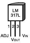
Here the Pin configuration of LM317L:
Download this car cigar lighter to USB circuit in PDF Version:
Do you have a bicycle..? why don't try to build this circuit..?. Powered using battery…
This is the circuit diagram of 3A switching power supply regulator: Simple and cheap, the…
Here is the remote control tester circuit. This circuit is really a simple and easy…
This is the circuit diagram of current output multiplier designed for regulator IC LM78xx. By…
The following diagram is the FM tracking transmitter based on 4 transistors. No additional notes…
This is the circuit diagram of white line follower toy. The actuator of the toy…