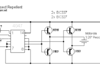
This insect repellent circuit will repel insects such as mosquitoes, flies and cockroaches from your home or yard effectively. circuit uses a specific frequency to disrupt the insect so the insect will go away from this […]
Category: Misc
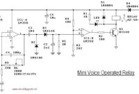
Mini Voice Operated Relay
This is the circuit diagram of a voice operated relay. It similar with sound activation switch circuit which will turn on and turn off (connect and disconnect) the switch depending on the sound input. The output […]
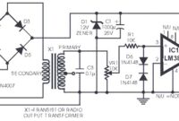
Telephone Amplifier using LM386
The following diagram is the circuit diagram of telephone amplifier, build based small amplifier IC LM386. This is a easy build telephone amplifier There is no extra electrical power supply required to power up the telephone […]
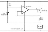
Safe Constant Current Source
In the above circuit diagram, a CMOS operational amplifier (op-amp) controls the current via a P-Channel HEXFET power transistor (IRF9520) to maintain a constant voltage across R1. The current is given by: 1 = VREF/R1. The […]
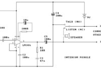
Two Station Intercom based on LM386
This a two station intercom. It uses two wires to run between each intercom unit. Each is self contained with its own battery, speaker, microphone and amplifier circuit. An LM386 audio power amplifier is used. It […]
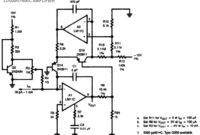
Logarithmic Amplifier LM11C
This is a logarithmic amplifier circuit based on National operational amplifier LM11C. Unusual frequency compensation provides this logarithmic converter a 100 us time continual from 1 mA down to 100 uA, escalating from 200 us to […]
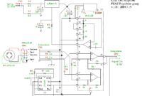
Load Cell Amplifier
I’ve found some interesting schematic of load cell amplifier. As we know, load cell amplifier is pretty expensive with fair price range of 100-300 USD. You may built your own load cell amplifier to get the […]
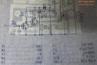
220V Touch Switch
This is a circuit of a touch switch used to turn on and turn off the electronic device that is connected to the 220V home electrical installations. This is a very simple circuit which use SCR […]
Delayed Turn-on Relay Switch
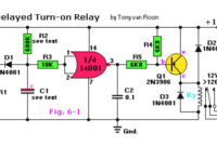
Here the circuit schematic of a delayed turn-on relay driver. It has capability to produce adjustable time delays for up to several minutes with reasonable accuracy.
Diode Zener Tester
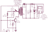
This is the circuit diagram of zener diode tester which tests zener diodes with breakdown voltages extending up to 120 volts. This is a handy circuit and will help you to measure the zener diode easily. […]

