- Version
- Download 1110
- File Size 191.71 KB
- File Count 1
- Create Date
- Last Updated September 19, 2016
5 Band Graphic Equaliser Project
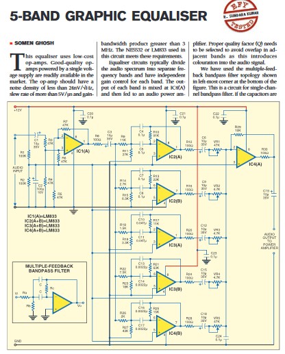
Equaliser circuits typically divide the audio spectrum into separate frequency bands and have independent
gain control for each band. The output of each band is mixed at IC4(A) and then fed to an audio power amplifier. Proper quality factor (Q) needs to be selected to avoid overlap in adjacent bands as this introduce colouration into the audio signal.
The potmeters (VR1 through VR5) are in the signal path and hence should be of the best quality possible. Wrap the body of the pots with bare copper wire and solder the other end of the wire to ground. Since the filters are very sensitive, all resistances should be metal-film type and the capacitors should be polyester type.
Each stage of the op-amp needs to be capacitively coupled to the next stage so that the DC does not get propagated and amplified. For a good low-frequency response, this coupling capacitor should be greater than 1 μF. A 10μF, 16V capacitor is used in each stage of the circuit here.
The circuit is powered by a 12V DC regulated supply. A well-regulated supply using 7812 is recommended. Ground the Vcc pin of each op-amp with a 0.1μF ceramic disk capacitor to bypass the noise.


