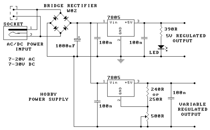
Hobby power supply for electronic hobbysts. This is power supply circuit which have 2 output that are static output and adjustabled output. The static output is stabled and regulated output.
The circuit is based around the 7805 voltage regulator. It has only 3 connections (input, output and ground) and it provides a fixed output. The last two digits of the part number specify the output voltage, eg. 05, 06, 08, 10, 12, 15, 18, or 24. The 7800 series provides up to 1 amp load current and has on-chip circuitry to shut down the regulator (rather than blowing out) if any attempt is made to operate it outside its safe operating area. (If this happens to you, let the chip cool down & attach the heatsink.)
It can be seen that there are in fact two separate circuits in this power supply. One 7805 is directly connected as a fixed 5V regulator. The second 7805 has a resistor divider network on the output. A variable 500R potentiometer is used to vary the output voltage from a minimum of 5V up to the maximum DC voltage depending on the input voltage. It will be about 2V below the input DC voltage.)
The capacitor across the output improves transient response. The large capacitor across the input is a filter capacitor to help smooth out ripple in the rectified AC voltage. The larger the filter capacitor the lower the ripple.
For small applications the heat sinks will not be needed. The tab on the regulator will dissipate 2W at 25 degree Celcius just in air. (This is equivalent, for example, to an input voltage of 9V, an output of 5V and drawing 500 mA.) However, as your projects get bigger they will draw more current from the power supply and the regulators will operate at a higher temperature.
Download this hobby power supply circuit manual in PDF version from the following link:
Do you have a bicycle..? why don't try to build this circuit..?. Powered using battery…
This is the circuit diagram of 3A switching power supply regulator: Simple and cheap, the…
Here is the remote control tester circuit. This circuit is really a simple and easy…
This is the circuit diagram of current output multiplier designed for regulator IC LM78xx. By…
The following diagram is the FM tracking transmitter based on 4 transistors. No additional notes…
This is the circuit diagram of white line follower toy. The actuator of the toy…
View Comments
i have lear more about electronics.
Hi I am an Iranian student project I made for my university needs to build a car battery charger circuit (car) Vjryan output voltage display on the LCD please help me I can just fast Batshkr site Khvbtan 22/12/2010 Email me najafkhanirasoul@yahoo.com
Great little starter power supply for the electronics hobbyist.
Want to learn more about electronics?
The GuruSantiago can help. Checkout his videos here:
http://www.youtube.com/user/ElectronicsIsFun
And follow him on twitter @ElectronicsFun