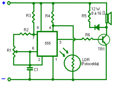
Here is the simple and low cost light alarm circuit built using timer IC 555 as the sound generator and a LDR to sense the environment light. This alarm is activated when the light beam on the LDR photocell is interrupted (You can use the light of a flashlight bulb which will make you a source for remain on, this may be 3 volts, no matter whether AC or DC).
Components List:
Capacitor:
C1: .1 uF
Resistor:
R1: 100K (potensiometer)
R2: 1K
R3: 47K
R4: 100K
R5. 27 ohm
R6: 220 ohm
Semiconductor:
IC1: 555
TR1: 2N3055, C1060 or C1226
D1: 1N4002
Others:
Speaker 8 or 16 ohms
1 LDR / photocell
When the LDR / photocell is receiving light, has low resistance, thus blocking the positive voltage that gives R4 to terminal 4 of IC 555, maintaining multivibrator off and the speaker does not sound when the photocell stops receiving light, its resistance increases in fraction seconds, which makes it reaches the above positive voltage to the terminal, which activates the alarm.
Circuit Note: The LDR should not receive another light than that which serves to activated.
Do you have a bicycle..? why don't try to build this circuit..?. Powered using battery…
This is the circuit diagram of 3A switching power supply regulator: Simple and cheap, the…
Here is the remote control tester circuit. This circuit is really a simple and easy…
This is the circuit diagram of current output multiplier designed for regulator IC LM78xx. By…
The following diagram is the FM tracking transmitter based on 4 transistors. No additional notes…
This is the circuit diagram of white line follower toy. The actuator of the toy…