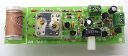
Here is the AM Radio receiver circuit diagram based on old single IC MK484.
Components List:
| R9, R10_________ 6R8 R6_____________ 100R R3_____________ 1K R1_____________ 4K7 R7_____________ 5K6 R4_____________ 10K R2_____________ 100K R5_____________ 150K R8_____________ 820K Pot_____________ 10K log pot Coil & ferrite bar set |
C7______________ 470p ceramic C, C4, C5, C6_____ 470nF monoblock C2______________ 100nF monoblock C3, C8___________ 100uF electrolytic capacitor VariCap__________ 60/160 AM tuning cap D1, D2, D3, D4____ 1N4148 diode Q1, Q3___________ BC548 Q2______________ BC558 IC1_____________ MK484 AM radio IC TO92 Speaker__________ 0.5 or 1W, 8 ohm speaker |
The MK484 we use is a Japanese copy of the original ZN414. It contains an RF amplifier, active detector and automatic gain control (AGC to improve sensitivity) all in a 3-pin package. The input impedence is typically 4M ohm. It operates over a range of 150kHz to 3MHz. DC supply of 1.1V to 1.8V & 0.3mA current drain makes it ideal for battery operation. The output is typically 40 – 60 mV of audio signal. Optimal AGC is provided by R3 and C2 (see Figure 2). R3 (the AGC resistor) should be in the range 100R to 1.5K. A bandwidth of about 4kHz is achieved.
Download the MK484 datasheet:
[wpdm_file id=52]
The MK484 is now a discontinued IC. It was made by New Japan Radio although it does not appear anywhere on their website(s). You may try to find the equivalent IC for MK484.
Download the complete explanation of this AM radio receiver circuit:
[wpdm_file id=53]
Do you have a bicycle..? why don't try to build this circuit..?. Powered using battery…
This is the circuit diagram of 3A switching power supply regulator: Simple and cheap, the…
Here is the remote control tester circuit. This circuit is really a simple and easy…
This is the circuit diagram of current output multiplier designed for regulator IC LM78xx. By…
The following diagram is the FM tracking transmitter based on 4 transistors. No additional notes…
This is the circuit diagram of white line follower toy. The actuator of the toy…