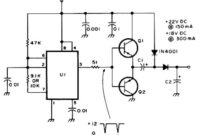
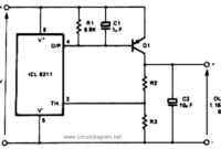
Here is the circuit diagram of active DC voltage doubler which used to increase the DC voltage. This circuit drives relays of 24 and 18VDC from a 12V power supply. Use this circuit can be work […]
Circuit Schematic Diagram
LM4809 105mW Stereo Headphone Amplifier
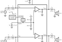
This is the stereo headphone amplifier circuit diagram, built based LM4809. This circuit can be used for stereo headphone amplifier circuit for home audio system, microphone preamplifier, personal computers and PDA headphone amplifier and more. The […]
5V Regulated Power Supply with OverVoltage Protection
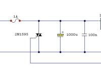
This is the circuit diagram of 5V Regulated Power Supply circuit, featured with over voltage protection. The circuit is based regulator chip 7805; Thyristor SCR 2N1595 and Dioda Zener 1N3997 for overvoltage protection circuit. The 5V […]
Telephone Amplifier using LM386
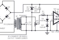
The following diagram is the circuit diagram of telephone amplifier, build based small amplifier IC LM386. This is a easy build telephone amplifier There is no extra electrical power supply required to power up the telephone […]
2 x 1.2W Dual Power Amplifier with KA2214
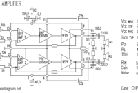
This is another stereo / dual power amplifier circuit with power IC KA series. This amplifier delivers dual power output (stereo) at 1.2W for each channel. General The KA2214 is a monolithic integrated dual audio power […]
Color Detector
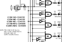
This is the color detector / sensor circuit diagram. This circuit will sense eight colors that are: green, red and blue (as primary colours); magenta, cyan and yellow (as secondary colours); and black and white. It’s […]
Safe Constant Current Source
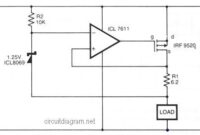
In the above circuit diagram, a CMOS operational amplifier (op-amp) controls the current via a P-Channel HEXFET power transistor (IRF9520) to maintain a constant voltage across R1. The current is given by: 1 = VREF/R1. The […]
Univox Super-Fuzz Pedal
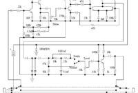
This is the circuit diagram of Univox Super-Fuzz Pedal. This pedal is actually a 69-to-early 70″s design that consists of two special capabilities. They are the octave generation effect from the differential-pair-with-collectors -tied-together along with the […]
Infrared (IR) Cordless Headphone
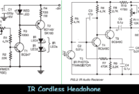
This is the schematic diagram of Infrared (IR) cordless headphone. Maybe it also can be called “wireless headphone”, but it use infrared as sound signal carrier. It use a pair of circuit diagrams that are IR […]
PNP Boost for Positive Voltage Regulator
This is the positive voltage regulator circuit with PNP Boost transistor: The IC8211 presents the voltage reference and regulator amplifier, while Q1 will be the series pass transistor. R1 defines the output current of the IC8211, […]

