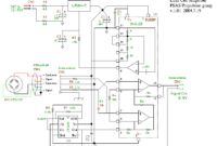
I’ve found some interesting schematic of load cell amplifier. As we know, load cell amplifier is pretty expensive with fair price range of 100-300 USD. You may built your own load cell amplifier to get the […]
Circuit Schematic Diagram
ATmega8535 Line Follower Robot
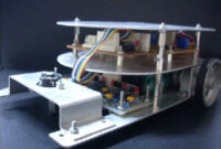
This is the circuit diagram of ATmega8535 Line Follower / Line Tracker robot. The circuit taken from the tutorial documentation. You may download the full tutorial at the end of this article. The ATmega8535 line follower […]
Sound Effect Generator UM3561
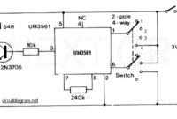
This is a really simple sound effect generator based single sound generator chip UM3561. The UM3561 will generate four kinds of sound effects. The basic operation is that the UM3561 will generate the sound signal, then […]
220V Touch Switch
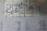
This is a circuit of a touch switch used to turn on and turn off the electronic device that is connected to the 220V home electrical installations. This is a very simple circuit which use SCR […]
1.3W RF Amplifier
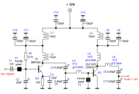
This diagram is a schematic diagram of RF amplifier circuit. The circuit will amplify the RF signal about 10 times, 100mW input power to 1.3W output power. It use a general NPN RF transistor 2SC1970. You […]
3-Rail (+12V) / (+5V) / (-5V) Regulated Power Supply
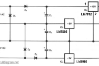
This circuit generates 3 source regulated voltages applying a minimum of electronic parts. The output DC voltage are +12V ; +5V and -5V. Diodes D2 and D3 conduct full-wave rectification, at the same time charging capacitor […]
Maestro Boomerang Pedal
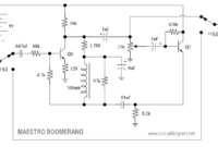
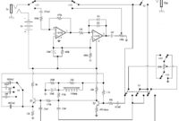
Here the circuit diagram of Maestro Boomerang pedal / Wah-Wah pedal for electric guitar effect. Note: Transistors Q1 and Q2 were designated P-2356. The Maestro Boomerang is not only a wide range wah wah pedal but […]
Simple Mixer 4 Input
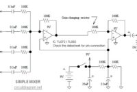
Here the simple mixer circuit with 4 inputs and 2 operational amplifier (op-amp) modules: A basic mixer suitable for mixing microphones or even effects outputs. The overall gain from input to output is one if the […]
Electro Harmonix Fuzz-Wah Guitar Effect
This is the electro harmonix fuzz-wah guitar effect pedal circuit diagram. Circuit Notes: Q1 & Q2 are 2n3565 Fuzz bypass S1 has been improved to provide true bypass S3 chooses volume or wah-wah S5 provides for […]
TDA7383: 4 x 35W Quad Bridge Amplifier
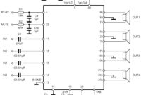
Here is the circuit diagram of 4 x 35W quad bridge amplifier. This is a power amplifier that has four input channels and four output channels or commonly called the quad amplifier. Power amplifier is designed […]

