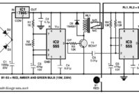
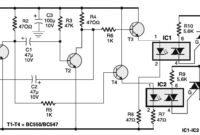
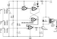
…composed of diodes D1 through D4, filtered by capacitor C1 and also regulated by IC 7805 (IC1). IC2 is wired as a multivibrator with ‘on’ and ‘off’ periods of about…
Search Results For: Assessor_New_V4 Excellect Pass Rate 😙 Assessor_New_V4 Latest Test Simulator 🏖 Assessor_New_V4 Exam Bible ◀ Search for ➤ Assessor_New_V4 ⮘ on ☀ www.pdfvce.com ️☀️ immediately to obtain a free download 🦦Premium Assessor_New_V4 Exam
Light Fence with LDR
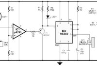
…power level and the voltage at the non-modifying include of IC1 will drop immediately. The yield of IC1 abruptly comes to be low, permitting T1 to direct. This triggers the…
Car Audio System Anti Theft Security
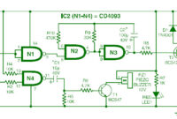
…time. You may make your own experiments as needed. Gate N4, with its associated components, forms a self-testing circuit. Normally, both of its inputs are in “high” state. However, when…
Smart Vibration Sensor Alarm
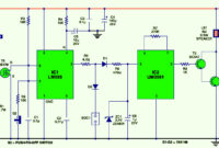
Here the circuit design of vibration sensor alarm. Initially, when power switch S1 is flipped to “on” position, power indicator LED1 lights up immediately. IC LM555 (IC1), wired as a…
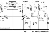
4 Stage FM Transmitter
…6, 5 and 7 turns of wire, respectively. This 4 stage FM transmitter tested by Electronics For You mag and should be work. You can download this circuit in PDF…
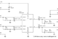
2x1W Stereo Amplifier with IC KA2209
…C2, C3______470uF/16V C4, C5______100uF/25V C6, C7______100nF IC__________KA2209/TDA2822 IC socket___8 pin The kit for this stereo audio amplifier circuit is available at elektronickits.com Download 2x1W Stereo Amplifier with IC KA2209 circuit…
Portable 230V Lamp Flasher
…the dangerous electrical shock, please be careful while constructing, testing or repairing. Download the Portable 230V Lamp Flasher circuit PDF document: 230V Lamp Flasher Project 1 file(s) 232.61 KB Download…
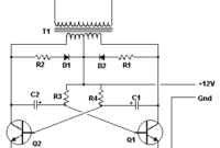
Basic Inverter
…depends the T1, T2 and transformer used. Please see the note. Basic Inverter Components list: Part Total Qty. Description Substitutions C1, C2 2 68 uf, 25 V Tantalum Capacitor R1,…
1.5V and 9V Battery Tester
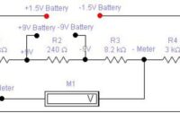
Here is the circuit diagram of battery tester designed by Matthew B.. This circuit can be used to measure the 1.5V and 9V battery. The circuit is very-very simple and…
Low Cost Water Pump Controller
…fast reaction, no wear and tear, and no mechanical problems. The circuit diagram can be seen on above image. The unit performed satisfactorily on a test run in conjunction with…

