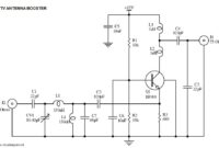
…to boost te UHF signal. Since this is an active circuit of UHF TV antenna booster, it will require a 12v power supply to operate. Regulated power supply is recommended…
Search Results For: Assessor_New_V4 Excellect Pass Rate 😙 Assessor_New_V4 Latest Test Simulator 🏖 Assessor_New_V4 Exam Bible ◀ Search for ➤ Assessor_New_V4 ⮘ on ☀ www.pdfvce.com ️☀️ immediately to obtain a free download 🦦Premium Assessor_New_V4 Exam
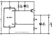
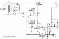
PNP Boost for Positive Voltage Regulator
This is the positive voltage regulator circuit with PNP Boost transistor: The IC8211 presents the voltage reference and regulator amplifier, while Q1 will be the series pass transistor. R1 defines…
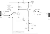
Vox Tone Bender Pedal
…a 15uF instead of a 25uF will reduce bass and it will also back off the fuzz some, too. The 50K “level” pot will also pass more treble compared to…
Sound Activated Light / Lamp
…power source, separate it adequate spacing with the other components. You may use common 12V DC power supply to operate this sound activated light circuit. Warning: This is High Voltage…
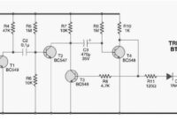
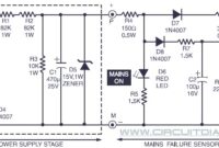
Power Supply Failure Alarm
…up to points “P” and “M” can be omitted from the circuit. Following points might be considered: At a higher DC voltage level, transistor T1 (BC558) may possibly pass some…
FM Wireless Microphone
…about 100 feet away. Your voice should still be heard over the radio. To obtain further distance, add a longer antenna. Download the FM Wireless microphone kit manual: [wpdm_file id=30]…
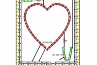
LED Flashing Heart
…cost, easy to built. Alternatively, you could be create another shape, not just heart shape. Schematic diagram: LED Flashing Heart Circuit Diagram Component list: Resistors R1, R2 – 470 ohm,…
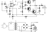
18W Audio Amplifier
…slew-rate Op-amp Q1 = BC182 50V 100mA NPN Transistor Q2 = BC212 50V 100mA PNP Transistor Q3 = TIP42A 60V 6A PNP Transistor Q4 = TIP41A 60V 6A NPN Transistor…
Adjustable Regulated Battery Charger
…flows through R8, a 100mV output is developed across it. The voltage developed across R8 is fed to one input of comparator U3. The other input of the comparator is…
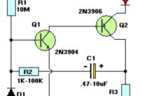
LED Flasher 2-Transistors
The following is LED Flasher circuit which use 2 transistors for LED switching. The circuit works similar to flip-flop operation. Components List: R1 = 10M ohm R2 = 1K –…

