Motor Related

PWM DC Motor Controller with MOSFET

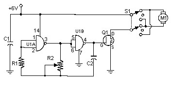
This is the simple and low cost pulse width modulation – PWM DC motor controller using a MOSFET. This kind connection for DC motor control is to prevent heat and minimize the power consumption. It controls the motor speed by driving the motor with short pulses. These pulses vary in duration to change the speed of the motor. The longer the pulses, the faster the motor turns, and vice versa.

PWM DC Motor Controller Component List

  • R1 1 Meg 1/4W Resistor
  • R2 100K Potensiometer
  • C1 0.1uF 25V Ceramic Disc Capacitor
  • C2 0.01uF 25V Ceramic Disc Capacitor
  • Q1 IRF511 MOSFET or IRF620
  • U1 4011 CMOS NAND Gate
  • S1 DPDT Switch
  • M1 Motor (See circuit notes)
  • MISC Case, Board, Heatsink, Knob For R2, Socket For U1

PWM DC Motor Controller Circuit Notes

  • R2 potensiometer to vary the speed of the oscillator and therefore the speed of M1.
  • M1 can be any DC motor that operates from 6V and does not draw more than the maximum current of Q1. The voltage can be increased by connecting the higher voltage to the switch instead of the 6V that powers the oscillator. Be sure not to exceed the power rating of Q1 if you do this.
  • Mount a heatsink on Q1 MOSFET.
  • Q1 in the parts list can handle a maximum of 5A. Use the IRF620 for 6A, if you need any higher.
circuit schematic

Share
Published by
circuit schematic

Recent Posts

Switched ON Bike Lamp

Do you have a bicycle..? why don't try to build this circuit..?. Powered using battery…

54 years ago

3A Switching Power Supply Regulator

This is the circuit diagram of 3A switching power supply regulator: Simple and cheap, the…

54 years ago

Remote Control Tester

Here is the remote control tester circuit. This circuit is really a simple and easy…

54 years ago

Current Output Multiplier for 78xx Regulator

This is the circuit diagram of current output multiplier designed for regulator IC LM78xx. By…

54 years ago

4 Transistor FM Tracking Transmitter

The following diagram is the FM tracking transmitter based on 4 transistors. No additional notes…

54 years ago

White Line Follower

This is the circuit diagram of white line follower toy. The actuator of the toy…

54 years ago