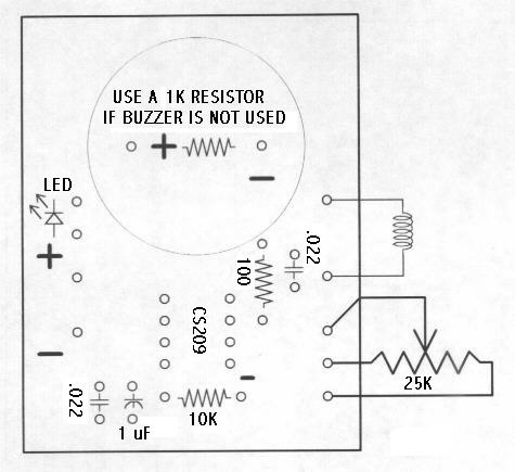
This is a very easy build, simple metal detector circuit, built based on a CS209A IC. The circuit will give surprising results and draws extremely small current from a 9 volt battery.
It worked great on the bench, but not so good outside for common metal detecting. But definately a great circuit for sensing studs in a wall, using the proper coil!
This certain circuit was built so it could be implemented with an LED and buzzer or only the LED or only the buzzer. battery voltage could be up to 20 volts, however it does not add to the sensitivity.
Additionally, modifications to the potensiometer value could be created, adding a smaller pot in series to create a extra sensitive trip point.
This circuit operates on the principal of adjustments in “Q” of the coil. So it’s crucial to attempt and make a High Q coil! But I discovered that even very simple coils gave fairly effective results! It’s suggested to work with “Litz” Wire, But I just applied vinal covered wire on 1 and also yet another with magnet wire and I got quite good results with both coils. Having now put a board together along with a couple of tests outside, it appears the coil requires a Faraday Shield.
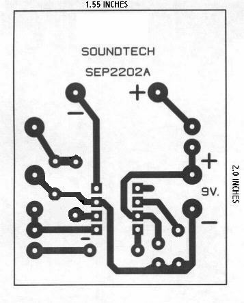
Complete explanation including the circuit board and PCB overlay, visit: chemelec.com
Do you have a bicycle..? why don't try to build this circuit..?. Powered using battery…
This is the circuit diagram of 3A switching power supply regulator: Simple and cheap, the…
Here is the remote control tester circuit. This circuit is really a simple and easy…
This is the circuit diagram of current output multiplier designed for regulator IC LM78xx. By…
The following diagram is the FM tracking transmitter based on 4 transistors. No additional notes…
This is the circuit diagram of white line follower toy. The actuator of the toy…