Image#1: Traffic Baton with LED Flasher Circuit
This is the traffic baton circuit which available in two versions that are traffic baton with LED flasher and traffic baton with bulb flasher. Both the circuits powered with a 6V, 4.5Ah rechargeable battery, which is clipped to the operator”s waistband. This circuit which come from EFY mag, will help the police or someone to regulate the traffic with hand signals at night or in dark condition. Since their hand signals may not be visible at night, it is necessary to have some illuminated direction indicator.
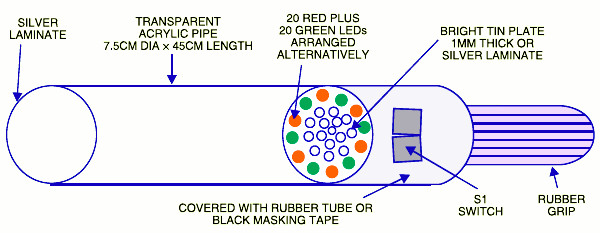
The image #1 displays the circuit of traffic baton with LED flasher. It uses an astable multivibrator to flash the LED, it similar to flipflof circuit. The “on” time of the LED cluster is about 108 milli seconds and “off” time is around 105 milliseconds. The frequency is around 5 Hz. A diode is wired in series with the base of BD140 to increase the forward voltage in order to ensure that when BD139 conducts, BD140 is cut-off. Select the LED which consumes low current (20 mA or so) but flashes bright.
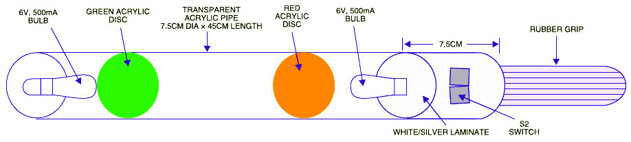
The image #2 displays the circuit of the trafic baton with bulb flasher. Similar with LED flasher version, the timer NE555 is wired as an astable multivibrator. The “on” period of flashing bulb is around 344 milliseconds and “off” period is around 329 milliseconds. The frequency is around 1.5 Hz. Bulb-driver transistors 2N3053/ BD139 and 2N2905/BD140 are used to light up the lamp. Two diodes are used in series with the base of 2N2905 to increase the forward voltage in order Bto ensure that when BD139 is conducting, BD140 is cut-off. Slide switch S2 is used to change the colour status of the flashing bulb.
Build the LED flasher and bulb flasher circuits on separate general- purpose PCBs. Place the LED flasher in a transparent acrylic pipe as displayed in above images. The bulb flasher circuit can be enclosed in another transparent acrylic pipe. Slide switches and red and green acrylic sheets are used for appropriate colour emissions.
Good luck.
Do you have a bicycle..? why don't try to build this circuit..?. Powered using battery…
This is the circuit diagram of 3A switching power supply regulator: Simple and cheap, the…
Here is the remote control tester circuit. This circuit is really a simple and easy…
This is the circuit diagram of current output multiplier designed for regulator IC LM78xx. By…
The following diagram is the FM tracking transmitter based on 4 transistors. No additional notes…
This is the circuit diagram of white line follower toy. The actuator of the toy…