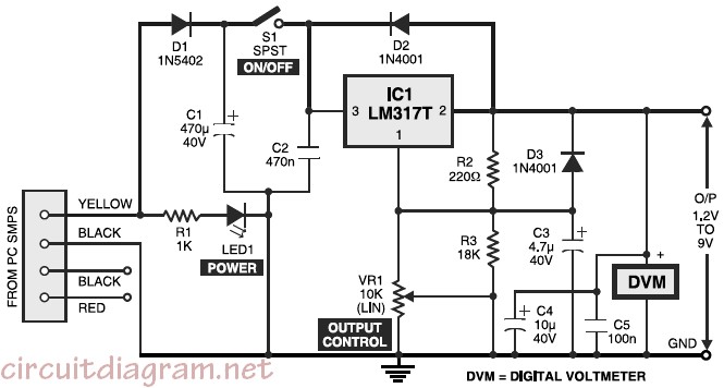
Here the variable desktop power supply which will convert a high input voltage (12V) from the SMPS / PSU of a desktop computer into small output voltage (1.25 to 9 volts). This converter will be very beneficial for electronics hobbyists. An adjustable three-pin voltage regulator chip LM317T (IC1) is applied right here to deliver the desired voltages. The LM317T regulator, in TO-220 pack, could deal with current of approximately 1 ampere in reality.
Above schematic diagram is the circuit of the variable desktop power supply. Regulator IC LM317T is set up in its standard application. Diode D1 protects against polarity reversal and capacitor C1 is an additional buffer. The green LED (LED1) signifies the status of the power input. Diode D2 keeps the output voltage from increasing above the input voltage when a capacitive or inductive load is hooked up at the output. Similarly, capacitor C3 eliminates any residual ripple.
Connect a common digital voltmeter in parallel with the output leads to precisely set the wanted voltage with the support of variable resistor / potensiometer VR1. It is possible to also work with your digital multimeter in case the digital voltmeter isn’t around. Switch on S1 and set the needed voltage through potensiometer VR1 and start reading it on the digital voltmeter. Now the power supply is all set to be used.
The circuit could be built on a general purposed Printed Circuit Board (PCB). Refer refer to the following picture for the pin configuration of LM317, just before soldering it on the PCB.
When the circuit already build, then enclose the circuit inside a metallic box, the suggested power supply box shown below:
Then open up the case of the desktop computer and hook up the input line of is circuit to a free available (hanging) four-pin drive power connector of the SMPS properly.
Do you have a bicycle..? why don't try to build this circuit..?. Powered using battery…
This is the circuit diagram of 3A switching power supply regulator: Simple and cheap, the…
Here is the remote control tester circuit. This circuit is really a simple and easy…
This is the circuit diagram of current output multiplier designed for regulator IC LM78xx. By…
The following diagram is the FM tracking transmitter based on 4 transistors. No additional notes…
This is the circuit diagram of white line follower toy. The actuator of the toy…