Linear Amplifier

120W Power Amplifier + Power Supply


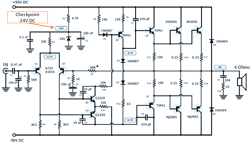
This is 120W power amplifier schematic using TO-3 package complementary transistors, NPN and PNP polarity. The well-known power transistor pair of 2N3055 and MJ2955 used in this circuit.  +/- 50V symmetrical (split/dual polarity) power supply with minimum 3A electric current should be used for maximum performance.

120W Power Amplifier Part List

Transistors

  • 2N3055 (substitution: MJ15003 or 2N3772) : 2
  • MJ2955 (substitution: MJ15004 or 2N3771) : 2
  • TIP42 : 2
  • TIP41 : 1
  • 2SC2229 or 2SC2230 or C1573 : 2
  • A1015 or A872 or A733 : 2

Capacitors

  • 100uF/50V electrolytic capacitor: 2
  • 470nF (474) nonpolar polyester capacitor: 1
  • 100pF (101) nonpolar ceramic capacitor : 2
  • 470pF (471) nonpolar ceramic capacitor : 2
  • 10pF nonpolar ceramic capacitor : 2
  • 100nF (104) 100V nonpolar polyester capacitor : 2

Resistors

  • 0.33 Ω (5W) : 4
  • 10 Ω to (1W) – brown, black, black : 1
  • 100 Ω (1W) – brown, black, brown : 2
  • 33 Ω (1/4W) – orange, orange, black : 1
  • 150 Ω (1/4W) – brown, green, brown : 3
  • 10KΩ (1/4W) – brown, black, orange : 1
  • 1KΩ (1/4W) – brown, black, red : 1
  • 4.7KΩ (1W) – yellow, violet, red : 1
  • 68KΩ (1/4W) – blue, gray, orange : 1
  • 56KΩ (1/4W) – green, blue, orange : 1
  • 33KΩ (1/4W) – orange, orange, orange : 1
  • 3.3KΩ (1/4W) – orange, orange, red : 2

Diodes

  • 3A Diode 1N5404 : 2
  • 1A Diode 1N4007 : 3
  • Zener diodes between 20 and 24 volts : 1

Others

  • 3A fuse
  • small 3-pin (GP) connector
  • large 6-pin connector (Molex)
  • aluminum heatsink
  • potentiometer of 20K if you want to add volume control

120W Power Amplifier PCB Layout Design

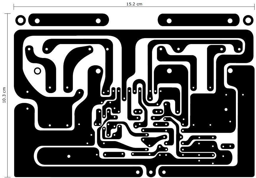
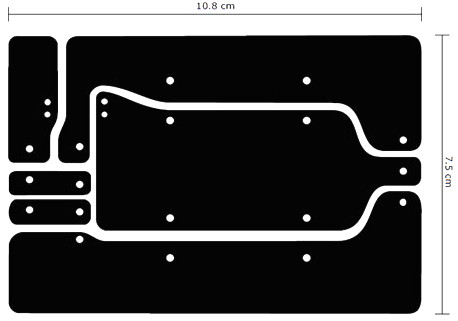
Bottom PCB Layout (Copper)

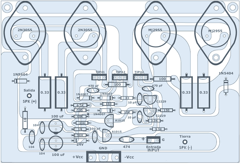
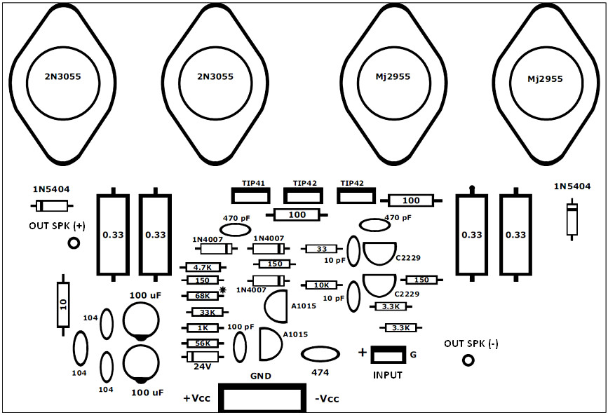
Top PCB Layout and Component Placement

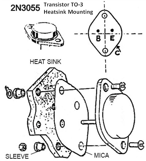
How to mount the transistors to the aluminium heatsink, see below image:

The points are: prevent circuit shortage, use proper isolator and use thermal compound for maximum heat spreading to the heatsink. Use mica between the transistor and the heatsink.

Power Supply Circuit for 120W Power Amplifier

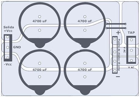
Power Supply Bottom PCB Layout

Power Supply Top PCB Design

Power Supply Part List

  • Transformer for the mono amplifier should be 35 + 35 volts AC with a minimum of 3 amps. If the stereo channel, the amperage should be doubled.
  • Capacitors of 4700 uF/63V: 4
  • Diode bridge (rectifier) ​​of 15 Amps: 1

120W Power Amplifier Wiring Connection

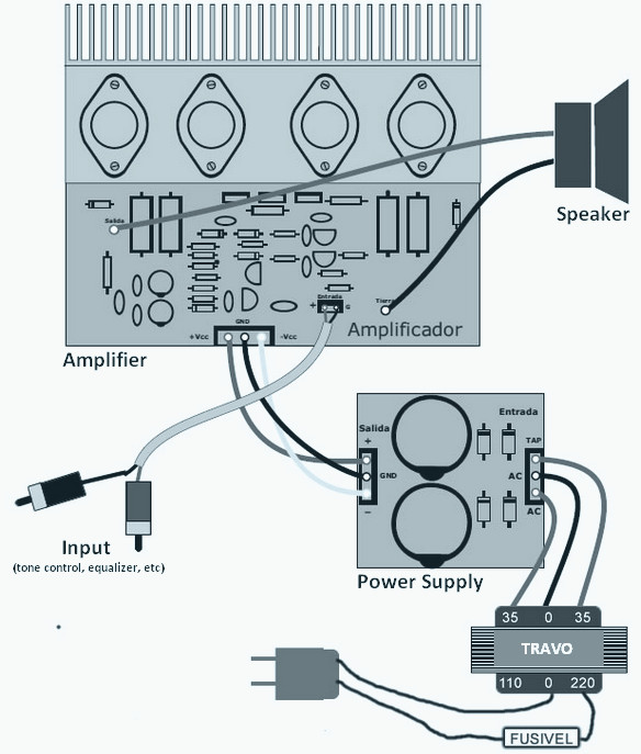
This is how to connect the amplifier module to the speaker, power supply and audio input. And connect the power supply module to the transformer.

circuit schematic

View Comments

Share
Published by
circuit schematic

Recent Posts

Switched ON Bike Lamp

Do you have a bicycle..? why don't try to build this circuit..?. Powered using battery…

54 years ago

3A Switching Power Supply Regulator

This is the circuit diagram of 3A switching power supply regulator: Simple and cheap, the…

54 years ago

Remote Control Tester

Here is the remote control tester circuit. This circuit is really a simple and easy…

54 years ago

Current Output Multiplier for 78xx Regulator

This is the circuit diagram of current output multiplier designed for regulator IC LM78xx. By…

54 years ago

4 Transistor FM Tracking Transmitter

The following diagram is the FM tracking transmitter based on 4 transistors. No additional notes…

54 years ago

White Line Follower

This is the circuit diagram of white line follower toy. The actuator of the toy…

54 years ago