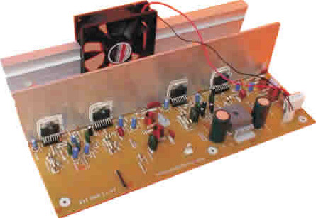
This is the 300W RMS stereo power amplifier circuit project. This amplifier is based four pieces of power IC TDA7294. It’s mean that every single channel of the circuit uses two ICs in bridge mode. In this application, the load value must not be less than 8 Ohms.
The main advantages of this solution are the following:
– High power with low voltage.
– Considerable power, even at high load values (Up to 16 Ohm).
With a load of 8 Ohms and a power supply voltage of ± 25V, the maximum performance that can be obtained is 150 W per channel. While with 16 Ohms load, and a power supply voltage of ± 35V, we will have a maximum of 170 W per channel.
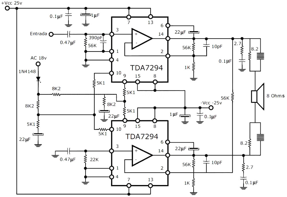
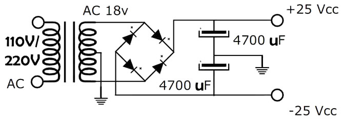
This 300W RMS stereo power amplifier require symmetrical power supply to work, the circuit diagram is included in this post.
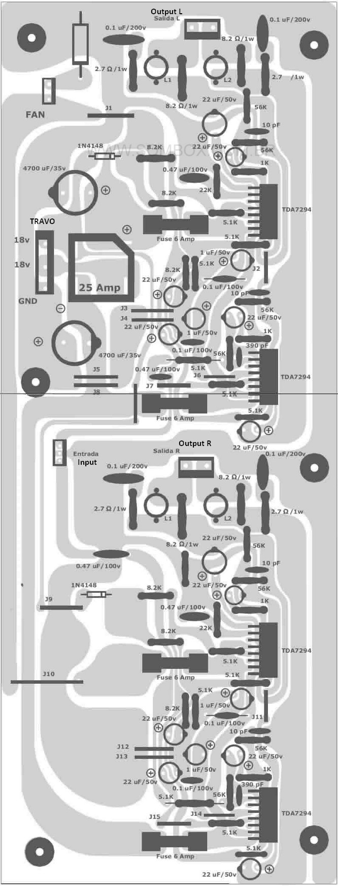
SEMI-CONDUCTORS
4 TDA 7294
RESISTORS
56K Ohms (green, blue, orange) : 8
8K2 Ohms (gray, red, red) : 3
5K1 Ohms (green, brown, red) : 14
8.2 Ohms 1W (gray, red, gold) : 4
2.7 Ohms 1W (red, purple, gold) : 4
22K Ohms (red, red, orange) : 2
1K Ohms (brown, black, red) : 4
CAPACITORS
4700 uF / 35v electrolytic capacitor : 2
22 uF / 35v electrolytic capacitor : 12
1 uF / 35v electrolytic capacitor : 4
0.1 uF / 250v polyester capacitor : 4
0.1 uF / 100v polyester capacitor : 4
0.47 uF / 100v polyester capacitor : 4
10 pF / ceramic capacitor : 4
390 pF / ceramic capacitor: 2
MISCELLANEOUS
25-amp diode bridge : 1
Diodes 1N4148 : 2
fuse holders for printed and 6 amp fuse : 4
small 3-pin connectors : 2
large 3-pin connectors : 2
small 6-pin connector : 1
18x18v to 12 Amp transformer : 1
Square mica insulation. : 4
coils of 10 coils with air core : 4
Of 1/4 inch and wire 18.
The resistance of the 12v cooler is calculated:
(15 / milliamperes of fan) = x Ohms.
Do you have a bicycle..? why don't try to build this circuit..?. Powered using battery…
This is the circuit diagram of 3A switching power supply regulator: Simple and cheap, the…
Here is the remote control tester circuit. This circuit is really a simple and easy…
This is the circuit diagram of current output multiplier designed for regulator IC LM78xx. By…
The following diagram is the FM tracking transmitter based on 4 transistors. No additional notes…
This is the circuit diagram of white line follower toy. The actuator of the toy…
View Comments
I like it
Hi,
Do you supply all the components for building a power amplifier? if so I am interested,
Moses Dabulamanzi