The following diagram is the FM transmitter circuit with FM transmision up to 4W. Voltage supply for this circuit is 12-16V with current consumption of 100-400mA. This circuit works with frequency of emission range of 88-108MHz. Transistor 2N2219 used as the main signal amplifier.
4 Watts FM Transmitter circuit design:
Components List:
R1, R2 = 10K Ohm (1/4 W)
R3 = 47 Ohm (1/4 W)
C1, C2 = 1nF
C3 = 4,7uF/16V
C4, C7, C8 = 0~45pF trimmer
C5, C6 = 10pF
C9 = 100nF
T1, T2 = 2N2219
ANT = Simple dipole l/2.
MIC IN = Microphone dynamic or other type. (It can also connected to a cassette player unit)
Inductor (L) specifications:
L1 = 4 turns, 7mm diameter *
L3 = 3 turns, 7mm diameter *
L4 = 5 turns, 7mm diameter *
L2 = RFC (resistance 1 MOhm with wrapped around her inductor of enough coils from fine isolated wire. Scratch of utmost inductor and you stick in utmost the resistance making thus a parallel L-r circuit.)
* The inductors is air from wire of coaxial 75W or other 1mm roughly.
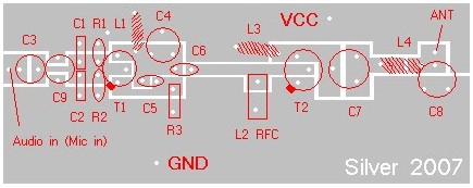
Component Placement:
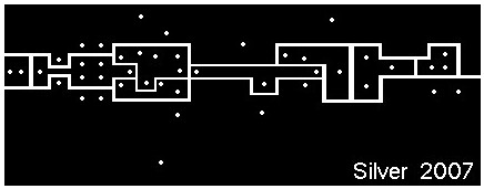
PCB Layout:
Download?2N2219 datasheet PDF document for 4 watts FM transmitter circuit reference:
Do you have a bicycle..? why don't try to build this circuit..?. Powered using battery…
This is the circuit diagram of 3A switching power supply regulator: Simple and cheap, the…
Here is the remote control tester circuit. This circuit is really a simple and easy…
This is the circuit diagram of current output multiplier designed for regulator IC LM78xx. By…
The following diagram is the FM tracking transmitter based on 4 transistors. No additional notes…
This is the circuit diagram of white line follower toy. The actuator of the toy…
View Comments
How do you do L2?
hæhæ 4 watt FM transmitter with 2 transistor 2n2219 I clicked the photo printed board this picture in actual size that I see on the screen? can you send me the correct width and length of the printing table in my email?
Is it really 4W output just oscilator n the Final only? I like it!
I USED 2N 2218,AT OUT PUT STAGE,WHICH GIVES MORE STABILITY.FINALLY GO FOR METAL BOX,TO AVOID INTERFERENCE.