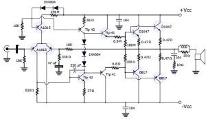
This is the schematic diagram of 400W RMS stereo power amplifier which use power transistor to work. This amplifier in addition to providing good sound power, also with excellent quality and a high fidelity with low noise, to obtain the 400 watts we can put 2 speakers of 4 Ohms or 4 of 8 Ohms. The circuit require symmetrical power supply.
400W RMS Stereo Power Amplifier Part List
Transistors:
D1047 – 4 pieces
B817E – 4 pieces
A1015 – 6 pieces
TIP41C – 4 pieces
TIP42C – 4 pieces
Resistors:
6.8 ohms – 1W (blue, gray, gold) – 4 pieces
100 ohms – 1W (brown, black, brown) – 4 pieces
18K – 1 / 2W (brown, gray, orange) – 4 pieces
1K – 1 / 2W (black brown, red) – 2 pieces
10 ohms – 1W (brown, black, black) – 4 pieces
270 ohms – 1 / 2W (red, violet, brown) – 2 pieces
10K – 1 / 2W (brown, black, orange) – 2 pieces
330 ohms – 1 / 2W (orange, orange, brown) – 2 pieces
56 ohms – 1 / 2W (green, black) – 2 pieces
27 ohms – 1W (red, violet, black) – 2 pieces
820 ohms – 1 / 2W (gray, red, brown) – 2 pieces
0.47 ohms – 5W – 8 pieces
Capacitors:
0.1uF/100v – 4 pieces
47uF/63v – 2 pieces
2.2uF/100v – 2 pieces
330pF (ceramic) – 2 pieces
4700uF/63v – 2 pieces
Miscellaneous:
Diode 1N4004 – 10 pieces
Diode P600J – 4 pieces
2 coils of 10 turns with 1/4 copper core 18.
7 amp 33x33v transformer – 2 pieces
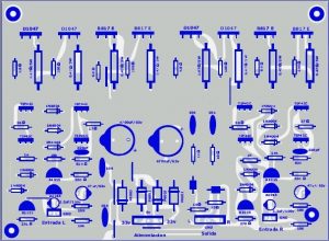
400W RMS Stereo Power Amplifier Top PCB Design
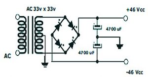
Power Supply Schematic for 400W RMS Stereo Power Amplifier
The power supply circuit is simple, you may use 10A transformer and 6800uf of capacitor. The diode value refer to the current value from transformer and it should be have higher value. For example if you use 7A transformer, then use 10A diodes.
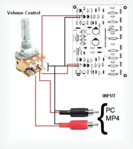
Input Connection with Volume Control
This is the input connection for 400W RMS stereo power amplifier with volume control using a stereo potensiometer.

what is the dimensions of the pcb?
can i use supply 42v 0 42v?
ATENCIÓN!!! … en el diagrama esquematico, están MAL puestos los nombres de algunos TIP41 y TIP42, por favor corrÍjan ese detalle, ya que quizá alguna persona sin experiencia previa, podría cometer errores CATASTROFICOS…
How to order this amplifier and where to order?
Please I want amplifier circuit to run horn 16 ohm 35 watt and 12-volt source is a car battery and will enclose some pictures of machine I know well I hope it’s a very bad attention please.