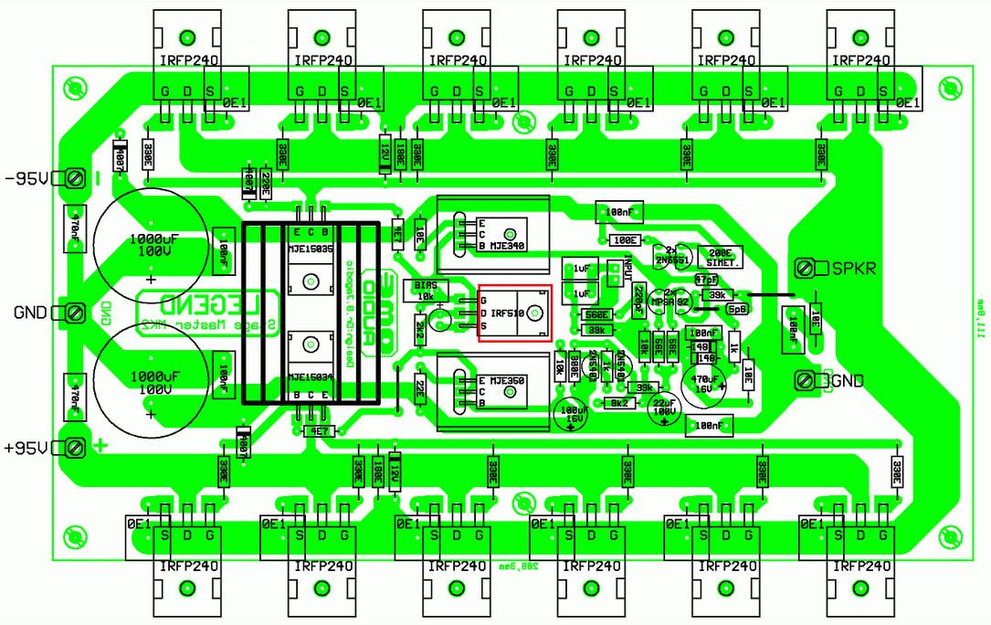
This is 500W RMS power amplifier circuit design, build based on MOSFET. The circuit is very popular in EE audio hobbyist as “LEGEND stage Master MK2”. It is a very good and powerful amplifier. It uses 12x power MOSFET IRFP240.
To achieve even greater power, and they were often interested young friends, was developed even stronger version is capable of producing a full and true 500W RMS into 8 ohms. With such large forces had to resort to a radically different solution some degree, for even better reliability, or has increased the complexity of the tiles so that for this version is impossible to use the same tile as the previous two lower models (Legend and Legend Stage Master).
Specification:
Output power ——— 500W RMS / 8 ohms
Frequency range 15Hz-130kHz (-1dB) at 30W RMS
THD = <0.18% (at 1 kHz and 500 W)
THD = <0.01% (at 1 kHz and 400W and below this power)
BIAS around 25mA per output pair
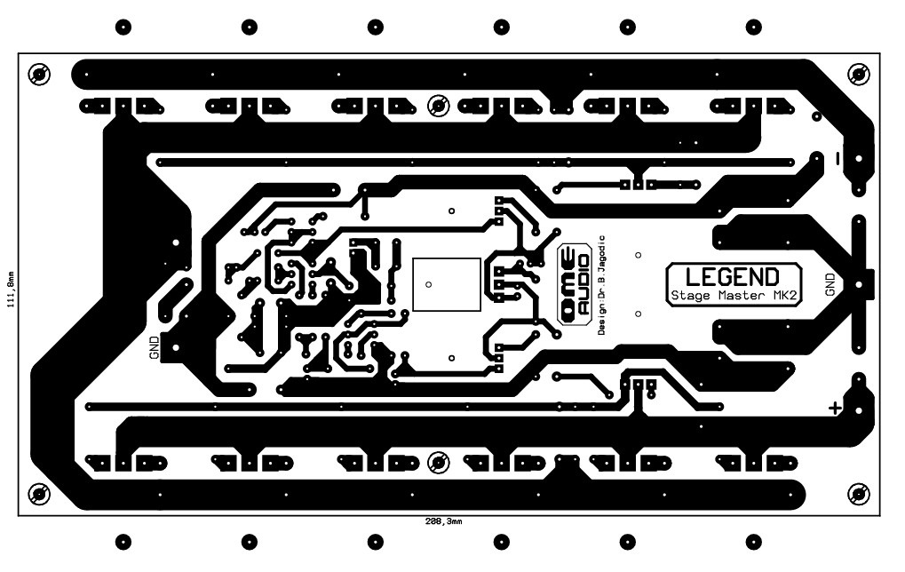
This is the PCB design and component placement, you should mount the MOSFET on the heatsink to prevent overheating and maintain the performance of power amplifier.
This circuit designed by Dr Borivoje Jagodic >> original page for the reference.
Do you have a bicycle..? why don't try to build this circuit..?. Powered using battery…
This is the circuit diagram of 3A switching power supply regulator: Simple and cheap, the…
Here is the remote control tester circuit. This circuit is really a simple and easy…
This is the circuit diagram of current output multiplier designed for regulator IC LM78xx. By…
The following diagram is the FM tracking transmitter based on 4 transistors. No additional notes…
This is the circuit diagram of white line follower toy. The actuator of the toy…
View Comments
CAN YOU SUPPLY ME WITH THE COMPLETED PCB AND COMPONENTS LAYOUT SO THAT I CAN BUILD THIS ONE, IF SO WHAT IS THE PRICE OF THE PCB AND SUPPLY ME WITH THE COMPONENTS ASWELL