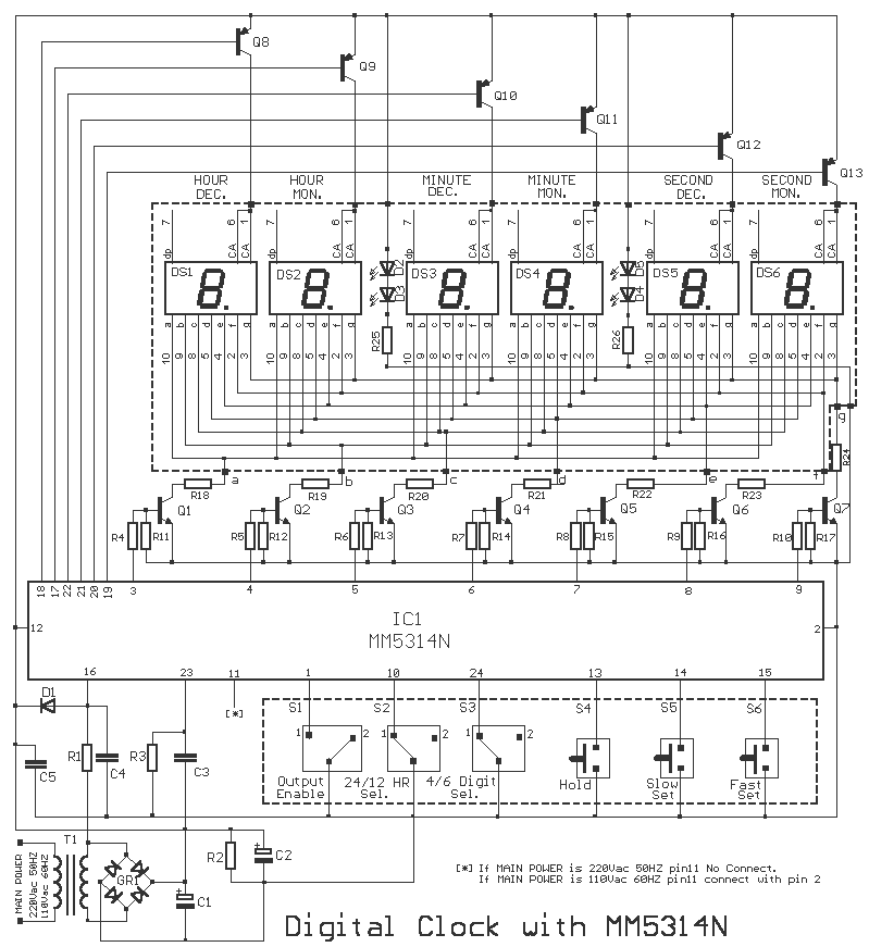
This is the circuit diagram of digital clock based on IC MM5314N. The clock display uses 6 pieces of 7 Segment LED with format HH:MM:SS. The power supply for this circuit already included, so you can connect this circuit directly to the mains. The DC supply is about 5-12V.
Parts List of Digital Clock Circuit:
R1 = 100Kohms
R2 = 47Kohms
R3 = 100Kohms
R4 ….. 10 = 2.2Kohms
R11 ….. 17 = 10Kohms
R18 ….. 24-25-26 = 220 ohmios
R25-26 = 1.2Kohms
C1 = 2200uF 25V
C2 = 100uF 25V
C3 = 18nF 100V
C4-5 = 10nF
D1 = 1N4148
Q1 a Q7 = BC550
Q8 a Q13 = BC560
IC1 = MM5314N ( Discontinue, National Semiconductor)
GR1 = 4X1N4002
T1 = 220V AC/12V 1A
DS1 a DS7 = Display Common Anodo
Datasheet document for digital clock IC MM5314N can be accessed here:
http://www.datasheetspdf.com/PDF/MM5314N/514207/1
Do you have a bicycle..? why don't try to build this circuit..?. Powered using battery…
This is the circuit diagram of 3A switching power supply regulator: Simple and cheap, the…
Here is the remote control tester circuit. This circuit is really a simple and easy…
This is the circuit diagram of current output multiplier designed for regulator IC LM78xx. By…
The following diagram is the FM tracking transmitter based on 4 transistors. No additional notes…
This is the circuit diagram of white line follower toy. The actuator of the toy…
View Comments
Can anyone please send me the pxb layout of this circuit on my mail is prateek839891@gmail.com
I shall be very thankful for her. I need this...