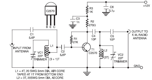
This is a simple low cost circuit of an active FM booster that can be used to amplify the FM band signal, so you can listen the FM channels/programs from distant FM stations clearly. The circuit make use of a common-emitter tuned RF preamplifier wired around VHF/UHF transistor 2SC2570. (Only C2570 is annotated on the transistor body).
For good result, you may construct the circuit on a good-quality PCB (preferably, glass-epoxy). The input/output trimmers (VC1/VC2) can be adjusted to get the maximum gain.
Input coil L1 consists of four turns of 20SWG enamelled copper wire (slightly space wound) over 5mm diameter former. It is tapped at the first turn from ground lead side. Coil L2 is similar to L1, but has only three turns. Pin configuration of transistor 2SC2570 shown on the above image.
This active FM booster circuit operated with 12V DC supply. You may use power supply or directly connected to the 12 lead acid battery.
Do you have a bicycle..? why don't try to build this circuit..?. Powered using battery…
This is the circuit diagram of 3A switching power supply regulator: Simple and cheap, the…
Here is the remote control tester circuit. This circuit is really a simple and easy…
This is the circuit diagram of current output multiplier designed for regulator IC LM78xx. By…
The following diagram is the FM tracking transmitter based on 4 transistors. No additional notes…
This is the circuit diagram of white line follower toy. The actuator of the toy…