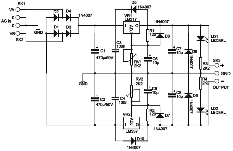
This is the circuit diagram of adjustable symmetric 1 to 24VDC, 1A Power Supply. This power supply give dual output positive and negatif output, you can adjust both positif and negative output (+1 to +24VDC and -1 to -24VDC). This kind of power supply also known as dual polarity power supply or splitted power supply which give positive anf negatif output.
This power supply can be used for universal usage, which required not more than 1A DC current. Please take a note that you should adjust the output voltage using general multimeter or DC voltmeter before use this power supply to protect the supplied devices.
Circuit Features:
Circuit Specifications:
Circuit Manual of Adjustable Symmetric 1 to 24VDC, 1A Power Supply:
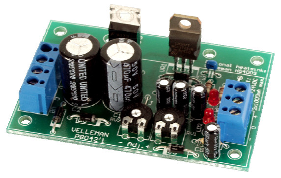
Kit Version:
This circuit available in kit version by valleman, you may purchase this kit online.
Do you have a bicycle..? why don't try to build this circuit..?. Powered using battery…
This is the circuit diagram of 3A switching power supply regulator: Simple and cheap, the…
Here is the remote control tester circuit. This circuit is really a simple and easy…
This is the circuit diagram of current output multiplier designed for regulator IC LM78xx. By…
The following diagram is the FM tracking transmitter based on 4 transistors. No additional notes…
This is the circuit diagram of white line follower toy. The actuator of the toy…
View Comments
I am very much thankful to you for circuit diagram for 24vdc,1amp,linear ,low ripple power supply,i want to know
where i will get ready kit of velleman.
Thanks and regards.
Mahendra Patil