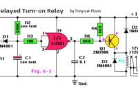
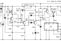
Here the circuit schematic of a delayed turn-on relay driver. It has capability to produce adjustable time delays for up to several minutes with reasonable accuracy.
Author:
Diode Zener Tester
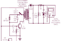
This is the circuit diagram of zener diode tester which tests zener diodes with breakdown voltages extending up to 120 volts. This is a handy circuit and will help you to measure the zener diode easily. […]
300W RMS Stereo Power Amplifier based IC TDA7294
This is the 300W RMS stereo power amplifier circuit project. This amplifier is based four pieces of power IC TDA7294. It’s mean that every single channel of the circuit uses two ICs in bridge mode. In […]
Stereo Tone Control with Line In + Microphone Mixer
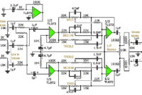
This is an active stereo tone control circuit using very well known op-amp IC of TL072. The circuit include mic pre-amp and mixer control. In this design, we have two inputs: one for line (stereo), one […]
100W Power Amplifier Based IC TDA7294
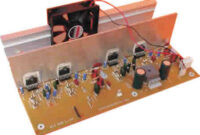
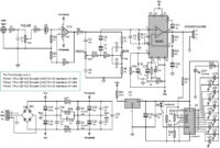
This is a very interesting circuit design to assemble. There are 4in1 amplifier module in a circuit board. 100W power amplifier using the TDA7294, for the VU meter uses IC LM3914. The tone control preamp uses […]
Triac, SCR, Transistor Tester
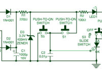
This is the circuit diagram of TRIAC, SCR and Transistor tester. This is a very simple circuit which can be used for testing of SCRs as well as triacs. The circuit could even be used for […]
Unipolar Stepper Motor Driver
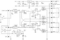
This is the circuit design of unipolar stepper motor driver to control unipolar stepper motors with 5, 6 or 8 wires. It uses four MOSFET IRFZ44. This circuit can be operated in free-standing or PC-controlled mode.
Glow Plug Control Module
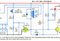
This is the glow plug control module unit to raise the air temperature inside the engine cylinder for quick and reliable starting, to extend the battery life and reduce the diesel consumption. In diesel engines, the […]
5VDC Single Polarity to 12VDC Dual Polarity Converter
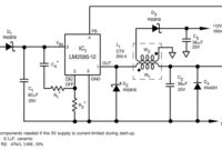
This is the circuit diagram of 5VDC single polarity to 12VDC dual polarity converter based on IC LM2595-12 from National Semiconductor. This circuit will convert 5V DC single voltage (+) become 12V DC dual polarity output […]
0-60V / 0-2A Variable Power Supply
This is the circuit diagram of 0-60V / 0-2A variable power supply. Of course this circuit used to cover the voltage range from 0 to 60V and current from 0 to 2A. The maximum current can […]

