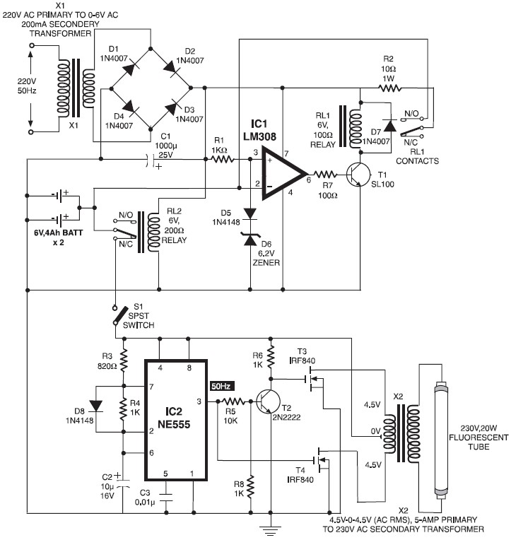
Automatic Switching-on Emergency Light Circuit.
When mains is absent, relay RL2 is in deenergised state, feeding battery supply to inverter section via its N/ C contacts and switch S1. The inverter section comprises IC2 (NE555) which is used in stable mode to produce sharp pulses at the rate of 50 Hz for driving the MOSFETs. The output of IC3 is fed to gate of MOSFET (T4) directly while it is applied to MOSFET (T3) gate after inversion by transistor T2. Thus the power amplifier built around MOSFETs T3 and T4 functions in push-pull mode.


Do you have a circuit design of an Automatic transfer switch for a portable generator?