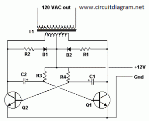
The following diagram is the basic design diagram of inverter circuit. The circuit will convert 12V DC to 120V AC. This basic inverter circuit can handle up to 1000Watts supply depends the T1, T2 and transformer used. Please see the note.
Basic Inverter Components list:
| Part | Total Qty. | Description | Substitutions |
| C1, C2 | 2 | 68 uf, 25 V Tantalum Capacitor | |
| R1, R2 | 2 | 10 Ohm, 5 Watt Resistor | |
| R3, R4 | 2 | 180 Ohm, 1 Watt Resistor | |
| D1, D2 | 2 | HEP 154 Silicon Diode | |
| Q1, Q2 | 2 | 2N3055 NPN Transistor (see “Notes”) | |
| T1 | 1 | 24V, Center Tapped Transformer (see “Notes”) | |
| MISC | 1 | Wire, Case, Receptical (For Output) |
Notes:
1. Q1 and Q2, as well as T1, determine how much wattage the inverter can supply. With Q1,Q2=2N3055 and T1= 15 A, the inverter can supply about 300 watts. Larger transformers and more powerful transistors can be substituted for T1, Q1 and Q2 for more power.
2. The easiest and least expensive way to get a large T1 is to re-wind an old microwave transformer. These transformers are rated at about 1KW and are perfect. Go to a local TV repair shop and dig through the dumpster until you get the largest microwave you can find. The bigger the microwave the bigger transformer. Remove the transformer, being careful not to touch the large high voltage capacitor that might still be charged. If you want, you can test the transformer, but they are usually still good. Now, remove the old 2000 V secondary, being careful not to damage the primary. Leave the primary in tact. Now, wind on 12 turns of wire, twist a loop (center tap), and wind on 12 more turns. The guage of the wire will depend on how much current you plan to have the transformer supply. Enamel covered magnet wire works great for this. Now secure the windings with tape. Thats all there is to it. Remember to use high current transistors for Q1 and Q2. The 2N3055’s in the parts list can only handle 15 amps each.
3. Remember, when operating at high wattages, this circuit draws huge amounts of current. Don’t let your battery go dead :-).
4. Since this basic inverter project produces 120 VAC, you must include a fuse and build the project in a case.
5. You must use tantalum capacitors for C1 and C2. Regular electrolytics will overheat and explode. And yes, 68uF is the correct value. There are no substitutions.
6. This circuit can be tricky to get going. Differences in transformers, transistors, parts substitutions or anything else not on this page may cause it to not function.


“Hi all,I have intex UPS for my desktop for 20mins backup. I want to increase the backup time to 1-2hrs. So one of my friend suggested me to use additional same battery as external Ups which can be connected with my current intex UPS whether it can be connected thru series or parallel? If i do like this will i face any problems? If yes what sort of problems? If i get answers for my above question i’ll be feel happy… Please help..”
please can you detail me on solar circuit diagram and inverter circuit diagram
sir plz send me full supll my home inverter diagram componet transformer autocut ups plz full detail me.thank u
i want home applicetion 12volts dc to 230volts ac circuit sir plese send me sir
Sir I have an UPS which is not working good it’s giving out 330vac. Can you please send me the 12vdc to 240vac 400w inverter circuit diagram so that I try to use this UPS transformer to it?
Thanks
can this company supply 5000kva inverters for some companies?
this ckt is a real simple ckt. how can i build a better one with high watt. i am thinking about building one that will give me alteast 3kw.
can u help me out with some siagrams.
Dear sir i need 825av invertor diagram andfalt find
Hi i need a diagram with parts and values for 12v dc to 220v ac 500/1000w inverter pls
dear sir, please explain in detail about inverter used in single phase circuit
Is that true that this inverter converts 12v dc to 120 v ac . What are the kind of switching elements that are used in this circuits are they mosfets, fets or thyristors.
Dear Sir
I think i is a nice progress. If you don’t mind, please give me estimate cost to design this inverter?.
Regard
Peter
pliz supply me with 1000-3000 watt circuit diagram
good job
sir, i need a three phase inverter circuit , which gives the output of three phase waveform.please also send me the simulation of the speed estimation of induction motor and position estimation of synchronous motor.which was done in MATLAB 7.1 or PSIM softwares.send me details of simulation circuit ,clearly to my mail id.
dear sir,
i am third year student i need a interesting and unique idea for my mini project pls give any idea with enough detail
Please I want to know if the diagram is for sine or square wave
this’s the bacis of inverter circuit diagram. How can i design my circuit well?
Sir, i need a simple ups circuit and methods to produce it. like that of ups of a computer.
hi, am arnold(+23408133813260) from the ambrose alli university ekpoma, nigeria. thanks for the diagram, anyways, i would please kindly ask if you can also give a full diagram for a 1kva inverter which can take over once there is power failure, as i live in an area with an epiletic poweer supply…thanks and God bless.