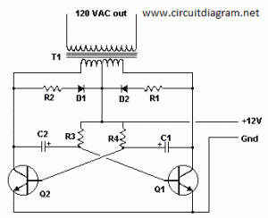
The following diagram is the basic design diagram of inverter circuit. The circuit will convert 12V DC to 120V AC. This basic inverter circuit can handle up to 1000Watts supply depends the T1, T2 and transformer used. Please see the note.
Basic Inverter Components list:
| Part | Total Qty. | Description | Substitutions |
| C1, C2 | 2 | 68 uf, 25 V Tantalum Capacitor | |
| R1, R2 | 2 | 10 Ohm, 5 Watt Resistor | |
| R3, R4 | 2 | 180 Ohm, 1 Watt Resistor | |
| D1, D2 | 2 | HEP 154 Silicon Diode | |
| Q1, Q2 | 2 | 2N3055 NPN Transistor (see “Notes”) | |
| T1 | 1 | 24V, Center Tapped Transformer (see “Notes”) | |
| MISC | 1 | Wire, Case, Receptical (For Output) |
Notes:
1. Q1 and Q2, as well as T1, determine how much wattage the inverter can supply. With Q1,Q2=2N3055 and T1= 15 A, the inverter can supply about 300 watts. Larger transformers and more powerful transistors can be substituted for T1, Q1 and Q2 for more power.
2. The easiest and least expensive way to get a large T1 is to re-wind an old microwave transformer. These transformers are rated at about 1KW and are perfect. Go to a local TV repair shop and dig through the dumpster until you get the largest microwave you can find. The bigger the microwave the bigger transformer. Remove the transformer, being careful not to touch the large high voltage capacitor that might still be charged. If you want, you can test the transformer, but they are usually still good. Now, remove the old 2000 V secondary, being careful not to damage the primary. Leave the primary in tact. Now, wind on 12 turns of wire, twist a loop (center tap), and wind on 12 more turns. The guage of the wire will depend on how much current you plan to have the transformer supply. Enamel covered magnet wire works great for this. Now secure the windings with tape. Thats all there is to it. Remember to use high current transistors for Q1 and Q2. The 2N3055’s in the parts list can only handle 15 amps each.
3. Remember, when operating at high wattages, this circuit draws huge amounts of current. Don’t let your battery go dead :-).
4. Since this basic inverter project produces 120 VAC, you must include a fuse and build the project in a case.
5. You must use tantalum capacitors for C1 and C2. Regular electrolytics will overheat and explode. And yes, 68uF is the correct value. There are no substitutions.
6. This circuit can be tricky to get going. Differences in transformers, transistors, parts substitutions or anything else not on this page may cause it to not function.


I want circuit diagram inverter
Dear Sir,
Can i use 6V,4.5AH battery to feed as input to this circuit, because i need to light up a 11W,230V CFL during power shut off. Or please suggest me a proper circuit for this circuit. Awaiting for your reply sir.
I am tying to repair an old toy that runs on batteries. What I am looking for is a circuit that will convert (invert) 9 volts DC to 3 volts AC 60 hz. low power output I know that it can be built using two transistors and an 555 timer ic. The problem is it has been so long since I have done anything like this, I have forgotten. Thanks in advance.
Hello people 🙂 I wondered if anybody knew if i could use wire wound resistors ? @ 5 watts i cant find bigger than 2w regular resistors
miloman – sm0vpo.com (harry L) I have made alot of his circuits, they have all worked exceedingly well for me..
inverter for 12v 7ah battery 200v 5a
dear sir ,is it possible to connect multiple batteries of 12v (car batterries) in series to produce about 220v dc then using a circuit to invert the 220v dc current to 220v ac current pls send me cicuit iam waiting for ur reply
sir,
i interested in electronics and i have a 45w cfl inverter which does not charge to battery. i open card of inverter, there 10uf 440v capacitor blown and i replace this by 46uf 440v capacitor but after this does not charging. please help….
I want to make 12v dc to 240v ac,500 watts inverter.plz send the message which requirements i need and send me circuits and parts name in my mail address
Hi I am interested in building this i have everything down pat except I was wondering were i should connect the fuse into the circuit and what size fuse should i use thanks
Dylan
by the way the power required to produce is around 1000-1200W
dear sir ,is it possible to connect multiple batteries of 12v (car batterries) in series to produce about 220v dc then using a circuit to invert the 220v dc current to 220v ac current ?if you have any circuit diagram please send .your prompt reply will be highly appreciated.
Der sir, iam chndra nd interested to make a home appliences inverter 12V DC to 230 VAC,500 Watt. Plas send me the circuit diagram of inverter
actualy you have done a very nice work. What is ur practical review? Kindly send me the cct. Diagram and the write up. Thanks for ur effort
I need one KVA inverter circuit digram
what about inverters made using PNP transistors otherwise i love your diagram keep sending them to me please
sir it can possible you send me Diagram of 500w to 5 kva Circuit Diagram i m from pakistan we use all Equipment AC 220v Standard.
i m waiting your fastest response my cell no is 0092321-8218844
Pls sir i need your phone number send it as soon as possible
Hi guys my name is kamal i am living in nigeria bauchi state.i have an inverter circuit which it is output is square wave so i want to change or convert square to sine wave.so i used with capacitor and inductor.so it can convert square to sinewave.for more details call me.08057583786 or mail me.kamalkmc12@yahoo.com
I am really highly impressed going through your website. It has often be my heart desire to try my hands on DC-AC inverter, going through your website has revived that I-can-do-it altitude in me. I would be very grateful if you could assist me with other necessary information/materials to fulfill my dreams. Also I will like you to throw more light on the effect of connecting induction load to DC/AC inverter.
I want to design an inveter of 5KVA for my project and I need your assistant,material.thanks