This is the electronic bicycle directional lights circuit that use inexpensive components and is a good substitute to many commercially available versions in the marketplace. This circuit works in an extremely different manner and is convenient to operate.
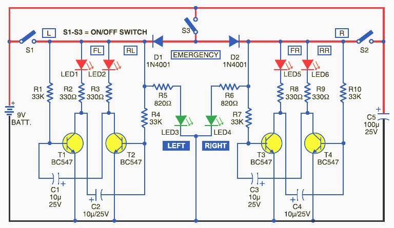
The bicycle direction indicators circuit works off a 9V PP3 (alkaline-type) battery and is basically a set of two independent free-running oscillators (astable multivibrators) built around four low-power transistors and a few passive components. Both the square-wave oscillators (one built around T1 and T2 and the other built around T3 and T4) drive four red LEDs (LED1 and LED2, and LED5 and LED6, respectively), which blink to indicate the direction of turn. Additional steady-glow LEDs (LED3 and LED4) are incorporated to indicate the working status.
When switch S1 is flipped to “on” position, DC supply from the battery is extended to the oscillator circuit formed by transistors T1 and T2. Now the left-side oscillator starts oscillating and the visual indicators at the front left (FL) and rear left (RL) start blinking at a rate determined by timing capacitors C1 and C2. Resistors R2 and R3 limit the operating current of LEDs (LED1 and LED2). At the same time, the green LED (LED3) starts glowing to indicate the present direction status.
Similar action happens in the next oscillator circuit built around transistors T3 and T4 when switch S2 is flipped to “on” position. Indicators at the front right (FR) and rear right (RR) start blinking, and at the same time the green LED (LED4) glows to indicate the direction status.
Switch S3 is used for emergency indication. When it is flipped to “on” position, both the oscillators get power supply through diodes D1 and D2. As a result, LED1 through LED6 start working simultaneously. In this condition, all the LEDs blink, except LED3 and LED4, which glow steadily.
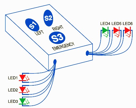
After assembling the circuit on a general purpose PCB, enclose it in a suitable cabinet as shown the following image and mount on the handle bar of the bicycle, preferably at the mechanical centre point.
Connect switch S1 at the left-hand side, S2 at the right-hand side and emergency switch S3 in the middle of the master unit. Now place this master unit at the top of the handle bar and do the essential interconnections using flexible wires. Connect the front indicators (LED1 and LED5) to the left and right side of the handle and similarly rear indicators (LED2 and LED6) can be mounted in the carrier frame of the bicycle.
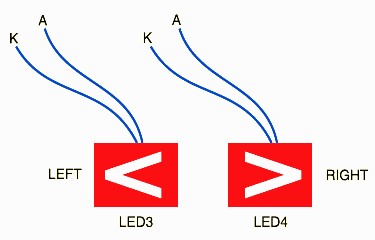
For the direction indicator, you can use the direction symbol and place it at the centre of the handle, look at above image for reference.
Do you have a bicycle..? why don't try to build this circuit..?. Powered using battery…
This is the circuit diagram of 3A switching power supply regulator: Simple and cheap, the…
Here is the remote control tester circuit. This circuit is really a simple and easy…
This is the circuit diagram of current output multiplier designed for regulator IC LM78xx. By…
The following diagram is the FM tracking transmitter based on 4 transistors. No additional notes…
This is the circuit diagram of white line follower toy. The actuator of the toy…