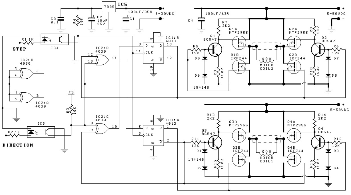
This bipolar stepper motor driver circuit will drive a bipolar stepper motor using externally supplied 5V levels for stepping and direction. These usually come from software running in a computer or from a microcontroller unit. The circuit uses IRFZ44 and MTP2955 MOSFET’s.
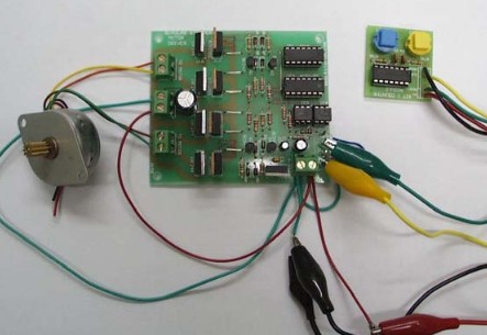
All the power inputs were connected together. The CLOCK was connected to STEP, and the RESET was connected to DIRection. Pushing the CLOCK button then advanced the motor one notch. Pressing CLOCK with the RESET button also depressed and pressed down advanced the motor one notch the other way.
Resistors 1/2W
R1, R2 : 1K
R3, R4 : 10K
R5, R6, R11, R12 : 12K
R7, R8, R13, R14 : 2K2
R9, R10, R15, R16 : 150R
C1 : 100uF/63V ecap
C2 : 10uF mini ecap
C3 : 100nF
D1-D8: 1N4148 diode
IC1 : 4013
IC2 : 4030
IC3, IC4 : 4N25
IC5 : 7805
Bipolar stepper motors have two coils and are controlled by changing the direction of the current flow through the coils in the proper sequence. These motors have only four wires.
The unipolar stepper motor is connected as a bipolar motor (the 2 center wires of the 6 wire motor are unused.) 9V was used. The STEP and DIRection negative inputpins were tied together and connected to system ground.
Kit for this bipolar stepper motor driver circuit is available.
Download kit manual in PDF:
Do you have a bicycle..? why don't try to build this circuit..?. Powered using battery…
This is the circuit diagram of 3A switching power supply regulator: Simple and cheap, the…
Here is the remote control tester circuit. This circuit is really a simple and easy…
This is the circuit diagram of current output multiplier designed for regulator IC LM78xx. By…
The following diagram is the FM tracking transmitter based on 4 transistors. No additional notes…
This is the circuit diagram of white line follower toy. The actuator of the toy…