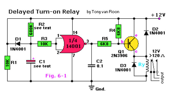
Here the circuit schematic of a delayed turn-on relay driver. It has capability to produce adjustable time delays for up to several minutes with reasonable accuracy.
R1,R3 = 10K
R2 = 680K (see text)
R4,R5 = 6K8
C1 = see text
C2 = 0.1μF, ceramic
Q1 = 2N3906, or equivalent
IC1 = 4001, or equivalent
D1,D2,D3 = 1N4001, or equivalent
Ry = Relay, 12V
The 14001 (or 4001) CMOS gate here is used to be a simple digital inverter. Its output is fed to the base of a regular 2N3906 (PNP) transistor, Q1, at the junction of resistor R5 and capacitor C2. The input to IC1 is taken from the junction of the time-controlled potential divider formed by R2 and C1. Before power is applied to the circuit, C1 is fully discharged. Therefore, the inverter input is grounded, and its output equals the positive supply rail; Q1 and RY1 are both off under this circuit condition. When power is applied to the circuit, C1 charges through R2, and the exponentially rising voltage is applied to the input of the CMOS inverter gate.
After a time delay determined by the RC time constant values of C1 and R2, this voltage rises to the threshold value of the CMOS inverter gate. The gate’s output then falls toward zero volts and drives Q1 and relay RY “ON”. The relay then remains on until you remove the power from the circuit. When that occurs, capacitor C1 discharges rapidly through diode D1 and R1, completing the sequence.
By varrying the values of C1 and R2, you will be able to control the time delay of the relay turning on process. The delay is approximately 0.5 seconds for every μF as value for C1. The delay can further be made variable by replacing R2 with a fixed and a variable resistor / potensiometer equal to that of the value of R2. Taken the value for R2 of 680K, it would be a combination of 180K for the fixed resistor in series with a 500K variable trimmer potensiometer. The fixed resistor is necessary so the series range value will be between 180K up to 680K.
Do you have a bicycle..? why don't try to build this circuit..?. Powered using battery…
This is the circuit diagram of 3A switching power supply regulator: Simple and cheap, the…
Here is the remote control tester circuit. This circuit is really a simple and easy…
This is the circuit diagram of current output multiplier designed for regulator IC LM78xx. By…
The following diagram is the FM tracking transmitter based on 4 transistors. No additional notes…
This is the circuit diagram of white line follower toy. The actuator of the toy…