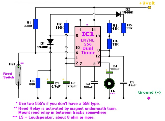
This is the circuit diagram of two tones train horn which built based dual timer IC NE556. The circuit is quite simple and easy to built and of course inexpensive. The circuit diagram is in a “basic” design, you may try to modify this circuit, for example: use a low power audio amplifier and use a small horn speaker 😀
R1 = 330K
R2 = 390K
R3,R6 = 68K
R4,R5 = 33K
C1 = 4.7μF/16volt, electrolytic
C2 = 2.2μF/16volt, electrolytic
C3 = 100nF, ceramic
C4 = 100μF/16volt, electrolytic
C5 = 47nF, ceramic
S1 = on/off switch
Re = Reed Relay (glass tube)
IC1 = NE556 (or use two 555’s) (I used a 2″/2W type)
D1,D2 = 1N4001
LS = 8 Ohm, 0.25-2watt. Others may work too.
Circuit is build up arround the LM or NE556 dual timer. Each timer producing a high or a low tone. The 556 contains two seperate 555 timers so feel free to use the 555’s. If you don’t want to fiddle with the reed relay that is fine too. Just put a push on-off switch between negative and pin 6 of IC1. If you go with the reed relay, mount a strong magnet underneath the locomotive and mount the reed relay somewhere between the tracks on a place where you want the horn to be sound. Make sure the reed relay is positioned in such a way that the magnet is able to close the contacts. Make sure reed relay contacts are facing upwards. The sound is very realistic.
C1 & C2 determine the duration (length) of the tones, C1 & C3 determine the frequencies. My original circuit was used
and modified for use with a R/C boat, I modified the caps in such a way it gave very low tones with a small 2″ speaker. Good luck…!
Do you have a bicycle..? why don't try to build this circuit..?. Powered using battery…
This is the circuit diagram of 3A switching power supply regulator: Simple and cheap, the…
Here is the remote control tester circuit. This circuit is really a simple and easy…
This is the circuit diagram of current output multiplier designed for regulator IC LM78xx. By…
The following diagram is the FM tracking transmitter based on 4 transistors. No additional notes…
This is the circuit diagram of white line follower toy. The actuator of the toy…