Categories: Radio

FETs based Micro-Spy

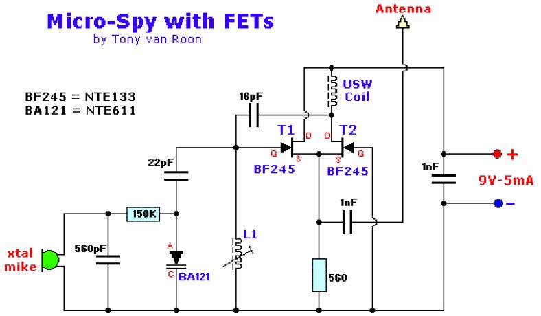
This is Micro-Spy circuit which designed using FET components..

Circuit Notes:

  • The FETs, T1 and T2, are BF245 N-channel FET’s model. It can be replaced with a NTE133 or ECG312. The BA121 varactor diode can be replaced with a ECG/NTE611. USW stands for ‘Ultra-Short-Wave’.
  • The oscillator has a frequency of approximately 100MHz.
  • L1 = 7 turns of 0.8mm Silverwire on a 5mm round Ferrit-core (adjustable).
  • Feedback via 16pF capacitor. No interference from antenna on resonance-loop.
  • Distance is at *least* 300 meters!

Micro-Spy circuit diagram by Tony Van Roon

circuit schematic

Share
Published by
circuit schematic

Recent Posts

Switched ON Bike Lamp

Do you have a bicycle..? why don't try to build this circuit..?. Powered using battery…

54 years ago

3A Switching Power Supply Regulator

This is the circuit diagram of 3A switching power supply regulator: Simple and cheap, the…

54 years ago

Remote Control Tester

Here is the remote control tester circuit. This circuit is really a simple and easy…

54 years ago

Current Output Multiplier for 78xx Regulator

This is the circuit diagram of current output multiplier designed for regulator IC LM78xx. By…

54 years ago

4 Transistor FM Tracking Transmitter

The following diagram is the FM tracking transmitter based on 4 transistors. No additional notes…

54 years ago

White Line Follower

This is the circuit diagram of white line follower toy. The actuator of the toy…

54 years ago