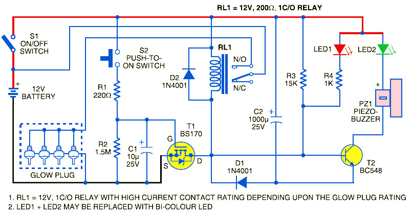
This is the glow plug control module unit to raise the air temperature inside the engine cylinder for quick and reliable starting, to extend the battery life and reduce the diesel consumption. In diesel engines, the air in the cylinders is not hot enough to ignite the fuel under cold conditions. Therefore every cylinder of these engines is fitted with an electric heater known as “glow plug”. A control module circuit is important to optimise the functioning of glow plugs.
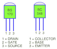
It utilizes a simple timer circuit built around MOSFET T1 for reliability and simplicity. Momentary pushing of switch S2 charges capacitor C1 rapidly via resistor R1. When the voltage on capacitor C1 exceeds the threshold voltage of the gate (G) of MOSFET T1, it starts charging reservoir capacitor C2 and simultaneously energises relay RL1. MOSFET T1 remains conducting as long as the voltage on C1 is greater than the threshold voltage of the MOSFET gate.
The “on” time period depends on the value of capacitor C1 and resistor R2, which govern the discharge current of capacitor C2. The component values given here will produce “on” time of around 25 seconds. In effect, when you press switch S2 momentarily, the relay energises for about 25 seconds and the glow plug gets the power supply through its contact.
The red LED (LED1) indicates that the heating process of glow plugs is “on”. When the “on” time is over, the green LED (LED2) turns on for a while, followed by a short beep from the buzzer, which indicates that the engine is ready for starting. Glow plugs draw a heavy current, hence high-current-rating contacts of an automotive relay are needed.
Build the glow plug control module unit on any general purpose PCB and mount it in a suitable case/box. Connect the glow plug wire to the relay contact. The 12V battery source that already available with the vehicle can be used to power the circuit. Connect the piezobuzzer and LED1 and LED2 through an external connection and place it at a convenient location for the driver to work.
Do you have a bicycle..? why don't try to build this circuit..?. Powered using battery…
This is the circuit diagram of 3A switching power supply regulator: Simple and cheap, the…
Here is the remote control tester circuit. This circuit is really a simple and easy…
This is the circuit diagram of current output multiplier designed for regulator IC LM78xx. By…
The following diagram is the FM tracking transmitter based on 4 transistors. No additional notes…
This is the circuit diagram of white line follower toy. The actuator of the toy…