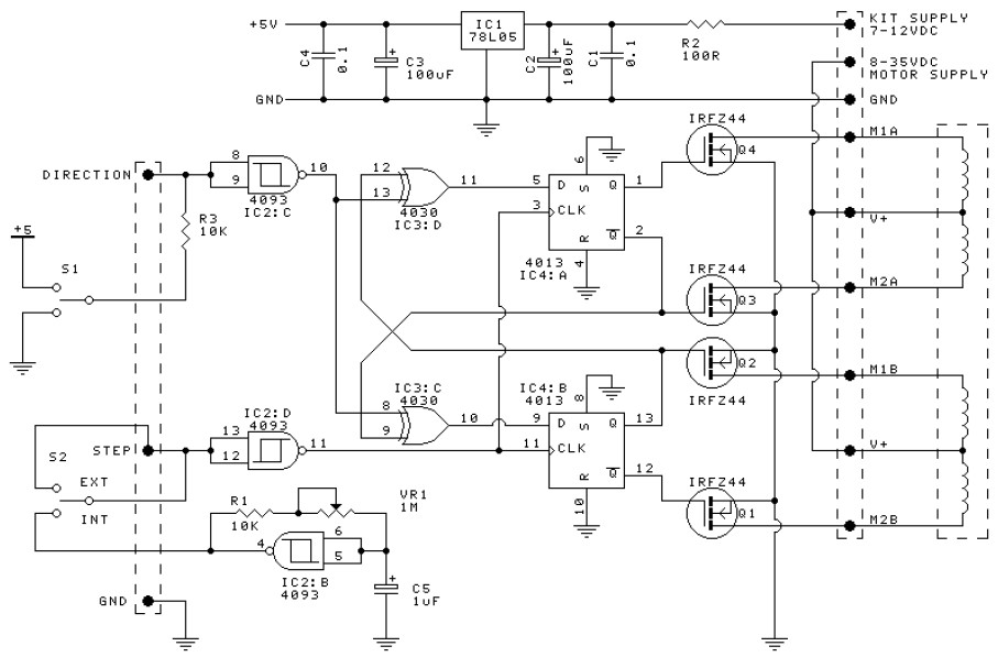
This is the circuit design of unipolar stepper motor driver to control unipolar stepper motors with 5, 6 or 8 wires. It uses four MOSFET IRFZ44. This circuit can be operated in free-standing or PC-controlled mode.
In free-standing mode an internal square-wave oscillator based on IC2:B of the 4093 supplies timing pulses to the OSC output. The frequency of these pulses and thus the speed of the stepper motor is controlled by the trimpot VR1 (100K.) A series 1K resistor controls the maximum frequency. You may increase the value of this resistor for your own needs. These pulses are fed into the STEP input which is buffered and inverted by IC2:D. This helps prevent false triggering. Similarly, IC2:C buffers and inverts the DIRection input. A SPDT taking the input to +5VDC or ground controls the direction of rotation.
IC3:C and D (4030 or 4070 exclusive OR gates) invert the outputs available at Q and /Q outputs of each of the flip-flops (FF) IC4:A and IC4:B. The incoming step-pulses clock the FF, thus toggling the Q & /Q outputs and this turns the MOSFET’s on and off in sequence. The IRFZ44’s have a low on-resistance and can deliver up to 6A each without needing a heatsink.
Power to the stepper motor is connected to V+ and GND terminals as shown on the overlay. There is a separate power supply, KITV, to the 78L05 to power the IC’s. 9V ??” 12VDC will be sufficient. R2/C2 form a low-pass filter to filter fast-rise switching transients from the motor.
Note that some stepper motor texts say to use a 4070 instead of a 4030. We have not worked out why this is. Certainly our testing with the 4030’s showed no problems. I would like to hear from anyone who knows why this advice is sometime given.
In computer-controlled mode use the three pads with pins DIR, STEP and GND. Switch the SPDT switch to EXTernal. The direction SPDT has no effect in external mode.
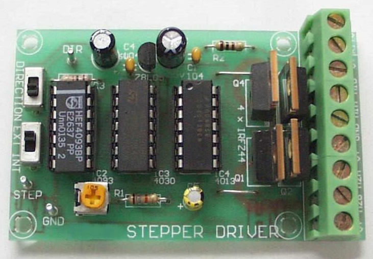
Kit for this unipolar stepper motor driver is available:
Download kit PDF manual (schematic, part list, explanation included):
Do you have a bicycle..? why don't try to build this circuit..?. Powered using battery…
This is the circuit diagram of 3A switching power supply regulator: Simple and cheap, the…
Here is the remote control tester circuit. This circuit is really a simple and easy…
This is the circuit diagram of current output multiplier designed for regulator IC LM78xx. By…
The following diagram is the FM tracking transmitter based on 4 transistors. No additional notes…
This is the circuit diagram of white line follower toy. The actuator of the toy…