Here is the simple and low cost NiCd and NiMH battery charger circuit which can be used for various battery type and size. This battery charger use a regulator IC of LM317.
Schematic diagram:
The charge will start if a battery is connected between pins JP1-JP4 or JP2-JP4 or JP3-JP4. For example, if a battery is connected to JP1-JP4 pins then the current that flows cause a voltage drop to R1, then D1 causes a voltage drop of 0,7 volts and ?1 conducts. Then through transistor’s emitter flows a current that comes from Adjustment pin of LM317.
NiCd – NiMH Battery Charger Circuit Notes:
|
Pins
|
Battery type
|
|
JP1 – JP4
|
AAA
|
|
JP2 – JP4
|
AA
|
|
JP3 – JP4
|
PP3 & 6F22
|
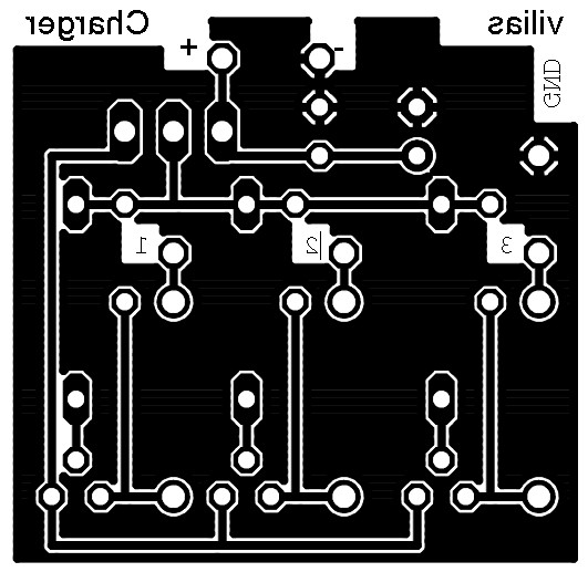
PCB top and bottom layout:
Do you have a bicycle..? why don't try to build this circuit..?. Powered using battery…
This is the circuit diagram of 3A switching power supply regulator: Simple and cheap, the…
Here is the remote control tester circuit. This circuit is really a simple and easy…
This is the circuit diagram of current output multiplier designed for regulator IC LM78xx. By…
The following diagram is the FM tracking transmitter based on 4 transistors. No additional notes…
This is the circuit diagram of white line follower toy. The actuator of the toy…
View Comments
I have a few doubts on this NiMH battery charger circuit.
>Is there any battery full auto cutt off protection in this circuit?
If not can you tell how can i implement this?