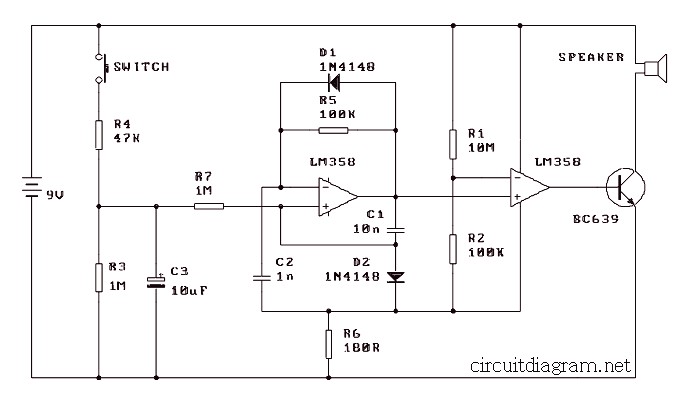
This is a low cost, simple, yet a surprisingly powerful electronic siren powered by just a 9V battery. The circuit may provide the final circuit block module in an alarm circuit using a relay to activate it.
When the switch is pressed C3 charges up through R4 with a time constant of 0.47 seconds. When the switch is released C3 begins a slower discharge through R7 and R3 with a time constant of about 5 seconds. The op amp is set up as a voltage controlled oscillator. The control voltage in this simple electronic siren circuit is the exponential rise and fall in the voltage of C3 as it charges and discharges.
When the output of the oscillator (pin 7) switches low, there is a charge remaining on C1 which holds pin 5 below the switching point. Current through R7 is proportional to the control voltage on C3. This current discharges C1 causing the voltage on pin 5 to rise towards the switching point at a rate proportional to the voltage on C3. When the switching point is reached pin 7 switches high, and initially pulls pin 6 high via C1. This causes the op amp to temporarily turn on hard. But C3 quickly recharges through D2 causing the voltage on pin 5 to fall below the switching point and causing the op amp to switch off again.
The positive pulse output from the op amp puts a fixed amount of charge into C2 slightly raising the potential of pin 6. This causes the potential on pin 6 to rise and assist the sharp switch off of the op amp. Also R5 & C2 delay the rise on pin 6 long enough to get a good output pulse.
The cycle then repeats. However, during the C3 discharge cycle the rate of charge of C1 is lower with each repetition of the oscillator (because the control voltage is lower) and the output frequency is correspondingly lower. During the C3 charge cycle the reverse applies.
The output pulses are buffered by a second op amp then the current is applied to a driver transistor. The output waveform has a low duty cycle, but gives a surprisingly loud sound.
The kit of this simple electronic siren based LM358 is available. Download the PDF version, part list included there…
Do you have a bicycle..? why don't try to build this circuit..?. Powered using battery…
This is the circuit diagram of 3A switching power supply regulator: Simple and cheap, the…
Here is the remote control tester circuit. This circuit is really a simple and easy…
This is the circuit diagram of current output multiplier designed for regulator IC LM78xx. By…
The following diagram is the FM tracking transmitter based on 4 transistors. No additional notes…
This is the circuit diagram of white line follower toy. The actuator of the toy…