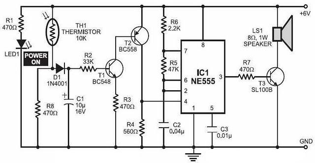
The following circuit is a simple fire alarm circuit based NE555 timer and use thermistor as a temperature detector. This sensor will activate the transistor when the temperature is in high value.
The thermistor will have a low resistance at high temperature, while at low temperature, the transistor resistance is high. This characteristic of thermitor is used to build the fire alarm.
The difference value of thermistor will decide the transistor 1 and transistor 2 to switching on or off, while TI and T2 has function to drive the NE555 to generate audio frequency. We can say that the thermistor’s condition (its sensing) will determine the alarm to be on or off. The T3 transistor used to drive the speaker so the audio frequency from NE555 can be heard by our ears.
This circuit powered using 6V DC supply. You may use battery or power supply adapter to supply this simple fire alarm circuit.
Do you have a bicycle..? why don't try to build this circuit..?. Powered using battery…
This is the circuit diagram of 3A switching power supply regulator: Simple and cheap, the…
Here is the remote control tester circuit. This circuit is really a simple and easy…
This is the circuit diagram of current output multiplier designed for regulator IC LM78xx. By…
The following diagram is the FM tracking transmitter based on 4 transistors. No additional notes…
This is the circuit diagram of white line follower toy. The actuator of the toy…
View Comments
What are the components please?
what is the temperature range of the thermisitor?
Gdday,my is not comment but question.I need to wire about 5 fire alarm with smoke detector.I need wiring diagram
can we replace SL100B with CL100S
I tried it and it worked