This is the simple project of small sound amplifier for ears or often called hearing aid device or hearing loss amplifier. This circuit was already tested on some patients and give significant improvement in the hearing ability to the patients. It consumes a very small amount of power within the range of 10 milliwatts. Furthermore, the voltage Requirement of every major component is within the range of 1.8 volts and 15 volts. Therefore, for portability, a 3V DC battery is used to power the circuit.
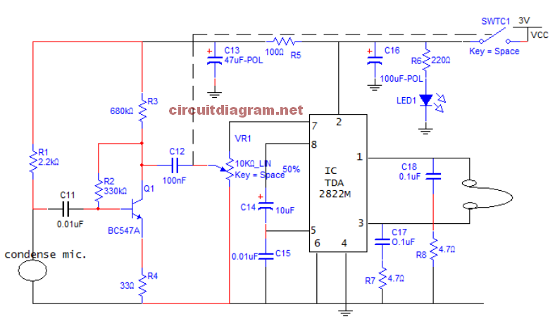
A 32 ohms earphone is used in the output unit of this project as recommended by the manufacturers of the TDA2822M IC. According to the IC’s datasheet, this 32 ohms earphone will produce an output of about 1.3 watts. In the circuit above, capacitors C11 and C12 are called coupling capacitors. Their functions are to block any DC components in the input and outputs of the pre-amplifier. The pre-amplifier comprises of R5 and capacitor c13 which decouples the power supply of the preamplifier stage, while capacitor C12 and resistors, R2, R3 and R4 with transistor T1 forms a negative feedback amplifier which stabilizes the overall gain (A). Resistor, R4 is known as an emitter swamping resistor which also adds stability to the amplifier. The medium power amplifier amplifies the output of the pre-amplifier to an audible level. It comprises of the TDA2822M IC and those external components needed to make the IC function properly. This other external components are capacitors C14, C15, C16, C17, C18 and resistors R6 and R7. Resistor, R5 and capacitor, C13 form an RC decoupling circuit which are connected across the power supply to smooth out noise. Finally a 32 ohms earphone is used in the output unit.
The components used are: condensed mic, 1=2.2kΩ, 2=330kΩ, 3 = 680kΩ,12 = 33Ω,
5=10kΩ, 6 =220Ω, 7=4.7Ω, 8 =4.7Ω, , 1 =BC547A , 1 =0.01,4=100, 3 = 47, 4 = 10, 5 = 0.01 , 6 = 100, 7 = 0.1, 8 = 0.1, V1=10kΩ, LED- Red, TDA 2822M, switch and battery (3V) and earphone.
The components for the sound amplifier for ears circuit were first assembled on a bread board and tested. After it was found to work as anticipated the components were transferred to a Vero board for the final construction.
Abstract: Hearing aid device is a small electronic gadget that is fit in or behind the ear to improve one’s hearing and consequently communication ability. This research work involves the design and development of a hearing aid device with pre-amplifier; an acoustic signal picked-up using a condenser microphone. TDA 2822M IC is configured to produce an audio amplification which is converted to audio signal through a headphone. Design equations were employed to calculate the physical parameters of the circuit. After the design, the circuit was constructed and tested on 5 people with partial hearing problem. The result showed that there was a significant improvement in the hearing ability of all the patients tested. Recommendations were proposed for further improvement.
Download: Small Hearing Aid Project Document | TDA2822M Datasheet
Do you have a bicycle..? why don't try to build this circuit..?. Powered using battery…
This is the circuit diagram of 3A switching power supply regulator: Simple and cheap, the…
Here is the remote control tester circuit. This circuit is really a simple and easy…
This is the circuit diagram of current output multiplier designed for regulator IC LM78xx. By…
The following diagram is the FM tracking transmitter based on 4 transistors. No additional notes…
This is the circuit diagram of white line follower toy. The actuator of the toy…
View Comments
hello, how were you able to simulate TDA2822M in Multisim or in any other program?
I have a project and I needed to simulate the IC but can't find the component in Multisim 14.0.
Send Help!!!