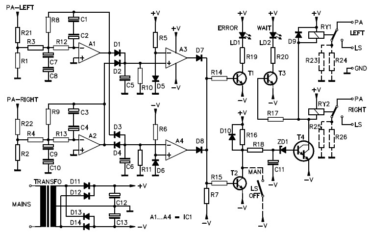
This is the speaker protection circuit, provides stereo speaker protection and prevents switch-on clicks and DC components on the output of the amplifier connected.
Speaker Protection Components List:
R1,R2 : 3K3
R3,R4,R5,R6,R7 : 8K2
R8,R9,R10,R11 : 330K
R12,R13 : 18K
R14,R15,R16,R17 : 47K
R18 : 47
R19,R20 : 680
R21,R22 : 100K
R23,R24,R25,R26 : 1K2
C1,C2,C3,C4,C5,C6 : 1uF
C7,C8,C9,C10 : 100uF
C11 : 220uF
C12,C13 : 470uF
D1,D2,D3,D4,D5,D6,D7,D8,D9,D10 : 1N4148
D11,D12,D13,D14 : 1N4007
ZD1 : 6V8
T1,T2,T3 : BC547B
T4 : BC517
LD1 : Red (ERROR INDICATOR)
LD2 : Yellow (WAIT INDICATOR)
RY1,RY2 : VR15M121C (12VDC – 15A – 1C)
Transfo (1,2VA – 2 x 6V / 2 x 0,1A)
IC1 : LM324
Circuit Notes:
This stereo loudspeaker protection will protect the loudspeakers against the switch-impulsions and the direct current component on the output of the connected amplifier.
Suitable for:
Specifications :
Download Speaker Protection Kit Manual Kit
Do you have a bicycle..? why don't try to build this circuit..?. Powered using battery…
This is the circuit diagram of 3A switching power supply regulator: Simple and cheap, the…
Here is the remote control tester circuit. This circuit is really a simple and easy…
This is the circuit diagram of current output multiplier designed for regulator IC LM78xx. By…
The following diagram is the FM tracking transmitter based on 4 transistors. No additional notes…
This is the circuit diagram of white line follower toy. The actuator of the toy…