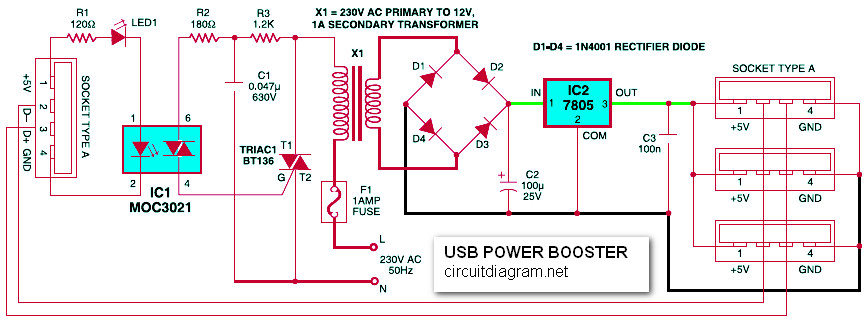
This is the circuit diagram of USB power booster, expecially to strength the power capability of USB port from PC / laptop / notebook. USB from PC can supply only a limited power to the external devices connected through its USB port, when too many devices are connected simultaneously, there is a possibility of power shortage. Therefore an external power source has to be added to power the external devices.
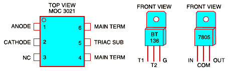
In USB, two different types of connectors are used: type A and type B. The circuit presented here is an addon unit, designed to add more power to a USB supply line (type-A). When power signal from the PC (+5V) is received through socket A, LED1 glows, opto-diac IC1 conducts and TRIAC1 is triggered, resulting in availability of mains supply from the primary of transformer X1. Now transformer X1 delivers 12V at its secondary, which is rectified by a bridge rectifier comprising diodes D1 through D4 and filtered by capacitor C2.
Regulator IC 7805 is used to stabilise the rectified DC. Capacitor C3 at the output of the regulator bypasses the ripples present in the rectified DC output. LED1 indicates the status of the USB power booster circuit.
Construct the circuit on a general purpose PCB and mount in a suitable box. Bring out the +5V, ground and data points in the type-A socket. Connect the data cables as assigned in the circuit and the USB power booster is ready to use.
Do you have a bicycle..? why don't try to build this circuit..?. Powered using battery…
This is the circuit diagram of 3A switching power supply regulator: Simple and cheap, the…
Here is the remote control tester circuit. This circuit is really a simple and easy…
This is the circuit diagram of current output multiplier designed for regulator IC LM78xx. By…
The following diagram is the FM tracking transmitter based on 4 transistors. No additional notes…
This is the circuit diagram of white line follower toy. The actuator of the toy…