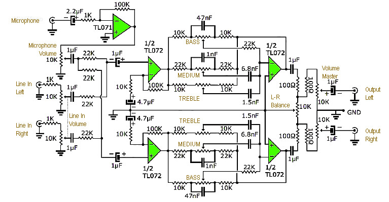
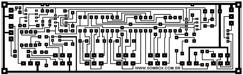
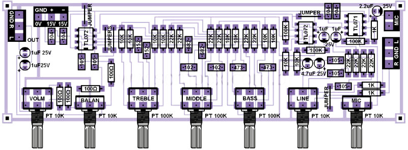
This is an active stereo tone control circuit using very well known op-amp IC of TL072. The circuit include mic pre-amp and mixer control. In this design, we have two inputs: one for line (stereo), one for microphone and has control of the three audio frequency (high/treble, medium and low/bass). It also provide balance control between right and left channel, microphone volume control, line in volume control and master volume for both line in and mic control. The circuit is powered by a regulated symmetrical power supply. The PCB layout design for both tone control and power supply is provided here, complete with component placement. Good luck.
INTEGRATED CIRCUIT
RESISTORS All 1/4W
CAPACITORS
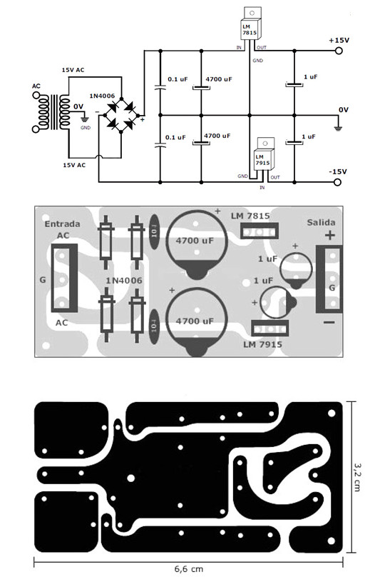
The power supply type for the stereo tone control is symmetrical and regulated and on its output we use +15 and -15 VDC. The LM7815 will deliver stabilized +15VDC and the LM7915 will deliver stabilized -15 VDC. For symmetrical source, the TL072 VCC range will be 7V up to 36V, so you may use a pair of regulator IC LM7805/LM7905 up to LM7815/7915.
Below is the schematic diagram, pcb design and component layout:
Do you have a bicycle..? why don't try to build this circuit..?. Powered using battery…
This is the circuit diagram of 3A switching power supply regulator: Simple and cheap, the…
Here is the remote control tester circuit. This circuit is really a simple and easy…
This is the circuit diagram of current output multiplier designed for regulator IC LM78xx. By…
The following diagram is the FM tracking transmitter based on 4 transistors. No additional notes…
This is the circuit diagram of white line follower toy. The actuator of the toy…
View Comments
how much size of pcb
Itu udah di uji bisa apa belum gan ..
Mohon balasan secepatnya.
Makasih